Method and device for calculating time difference between incident wave and reflected wave in traveling wave method positioning

A technology of incident waves and reflected waves, which is applied in the detection of faults and fault locations using the pulse reflection method, can solve the problems of low accuracy, achieve accurate results, reduce costs, and avoid economic losses

Active Publication Date: 2012-04-25
GUANGZHOU POWER SUPPLY BUREAU GUANGDONG POWER GRID CO LTD +1
View PDF3 Cites 19 Cited by
  • Summary
  • Abstract
  • Description
  • Claims
  • Application Information

AI Technical Summary

Problems solved by technology

[0010] The purpose of the present invention is to provide a method and device for calculating the time difference between the incident wave and the reflected wave in the positioning of the traveling wave method, which solves the problem of accurate results of the time difference between the calculated incident wave and the reflected wave in the positioning process of the current single-ended traveling wave method lower sex problems

Method used


Image

  • Method and device for calculating time difference between incident wave and reflected wave in traveling wave method positioning
  • Method and device for calculating time difference between incident wave and reflected wave in traveling wave method positioning
  • Method and device for calculating time difference between incident wave and reflected wave in traveling wave method positioning

Examples


Embodiment Construction

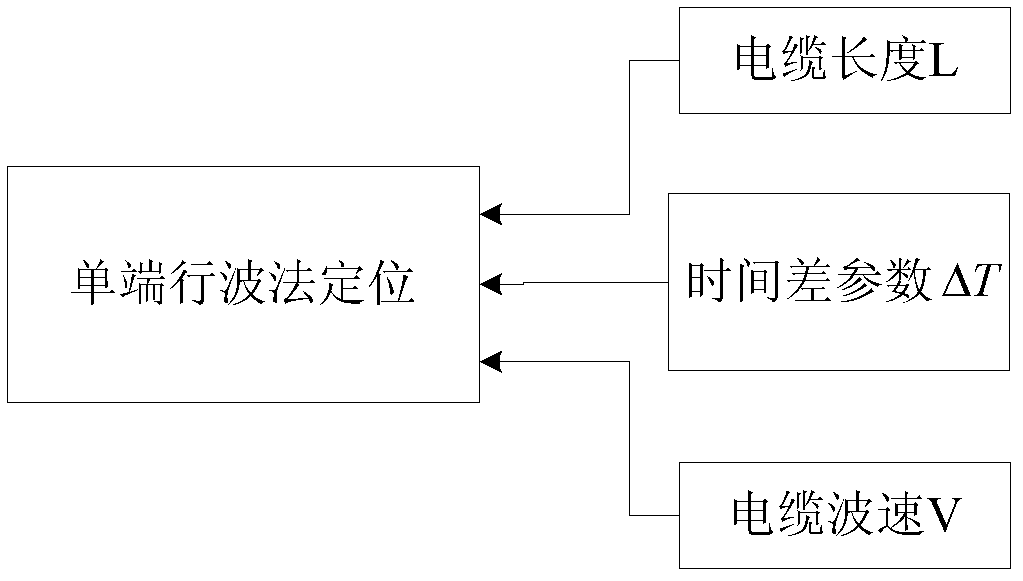
[0028] The technology for calculating the time difference between the incident wave and the reflected wave in the positioning of the traveling wave method of the present invention lies in the calculation of the ΔT process. Compared with the conventional traveling wave method positioning, the incident wave in the form of a pulse is used for measurement, and the incident pulse corresponding to the incident wave is calculated. The time difference between the reflected pulses determines the time difference between the incident and reflected waves.

[0029] The method for calculating the time difference between the incident wave and the reflected wave in the positioning by the traveling wave method of the present invention will be described in detail below with reference to the accompanying drawings and embodiments.

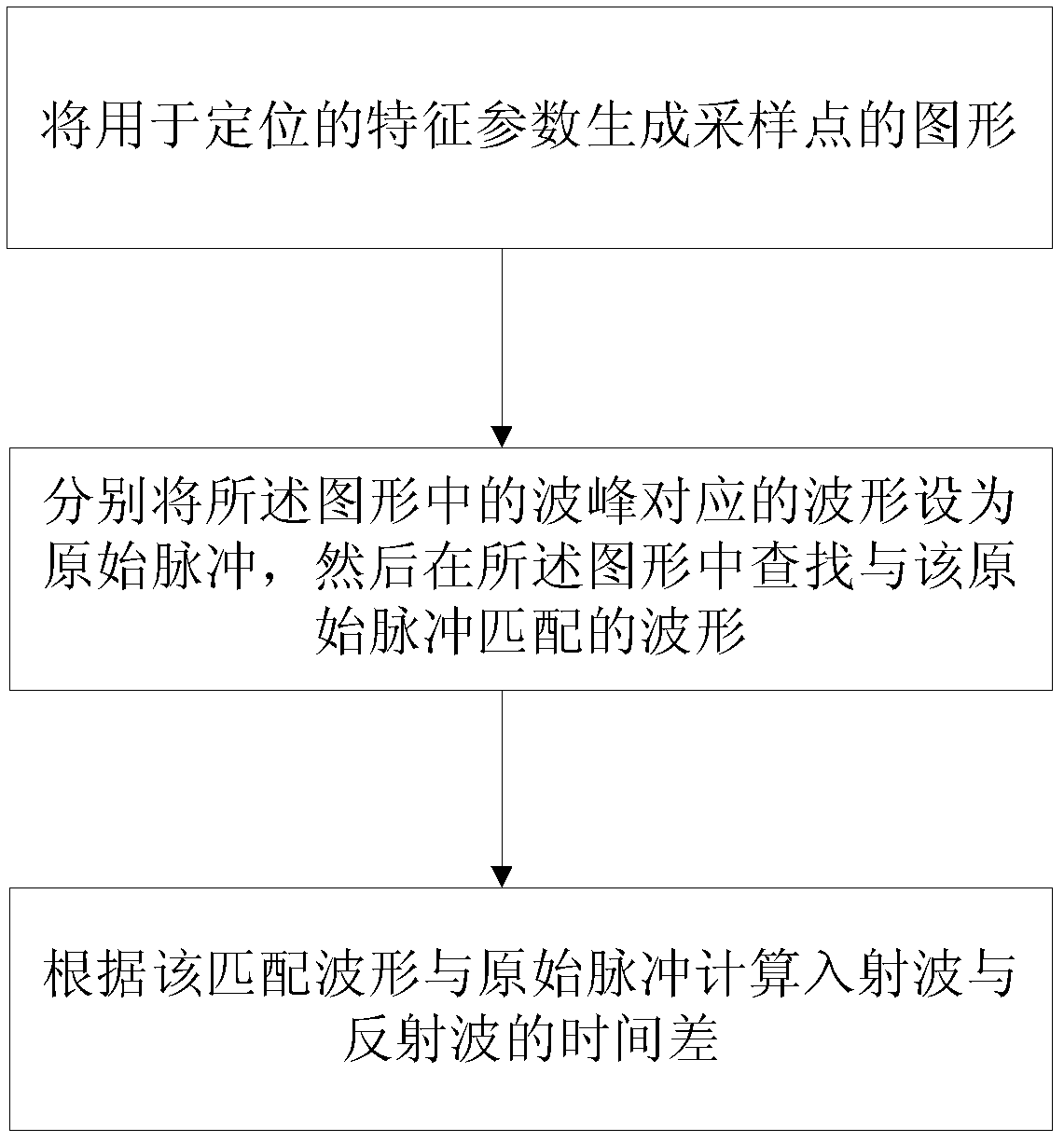
[0030] A method for calculating the time difference between the incident wave and the reflected wave in the positioning of the traveling wave method, such as image 3...


PUM


Abstract

The invention provides a method for calculating a time difference between an incident wave and a reflected wave in traveling wave method positioning. The method comprises the steps of: generating a pattern of sampling points from characteristic parameters for positioning; setting a waveform corresponding to a wave crest in the pattern as an incident pulse, and then searching for a waveform matching with the incident pulse in the pattern; and calculating the time difference between the incident wave and the reflected wave according to the matched waveform and the incident pulse. Furthermore, the invention provides a device for calculating the time difference between the incident wave and the reflected wave in the traveling wave method positioning. By means of the technology provided by the invention, the time difference which exists between the incident wave and the reflected wave and is needed in single-ended traveling wave method positioning is calculated; the result of a parameter value of the obtained time difference is more accurate; automatic calculation is realized in the entire process, and the incident wave and the reflected wave are unnecessary to calibrate by a tester depending on experience and intuition, so that a worker can judge conveniently; the economic loss caused by human errors is avoided; and the cost of manpower consumption is lowered.

Description

technical field [0001] The invention relates to a partial discharge detection technology of electric power cables, in particular to a method and a device for calculating the time difference between an incident wave and a reflected wave in positioning by a traveling wave method. Background technique [0002] Transmission lines, such as power cables and optical fibers, will show varying degrees of changes in physical properties when faults occur. The purpose of measuring the fault point of the transmission line is first to understand the characteristics of the transmission line when it is in normal use, and compare it with the characteristic value in the current operating state. The second is to find out the fault point if an abnormal situation is found. location of . For the transmission line in operation, the part with severe discharge can be replaced to ensure the safe operation of the line; if a serious defect is found in a certain section of the transmission medium being...

Claims


Application Information

Patent Timeline
Patent Type & Authority Applications(China)
IPC IPC(8): G01R31/11
Inventor 熊俊陆国俊宁宇田立斌叶加骅
Owner GUANGZHOU POWER SUPPLY BUREAU GUANGDONG POWER GRID CO LTD
Why Eureka
Try Eureka