Method and apparatus for determining reflective optical quality using gray-scale patterns

a technology of reflective optical quality and grayscale pattern, which is applied in the direction of optical apparatus testing, instruments, structural/machine measurement, etc., can solve the problem that the method is subject to errors, and achieve the effect of accurate and repeatable results

Inactive Publication Date: 2000-08-08
FORD GLOBAL TECH LLC +1
View PDF43 Cites 108 Cited by
  • Summary
  • Abstract
  • Description
  • Claims
  • Application Information

AI Technical Summary

Benefits of technology

The invention overcomes the shortcomings of the prior art by providing a method and apparatus for determining reflective optical quality of a reflective product at any and all points on the product. Furthermore, the method and apparatus provide accurate and repeatable results.

Problems solved by technology

This method, however, is subject to errors if reflective properties of the product are not uniform.

Method used


Image

  • Method and apparatus for determining reflective optical quality using gray-scale patterns
  • Method and apparatus for determining reflective optical quality using gray-scale patterns
  • Method and apparatus for determining reflective optical quality using gray-scale patterns

Examples


Embodiment Construction

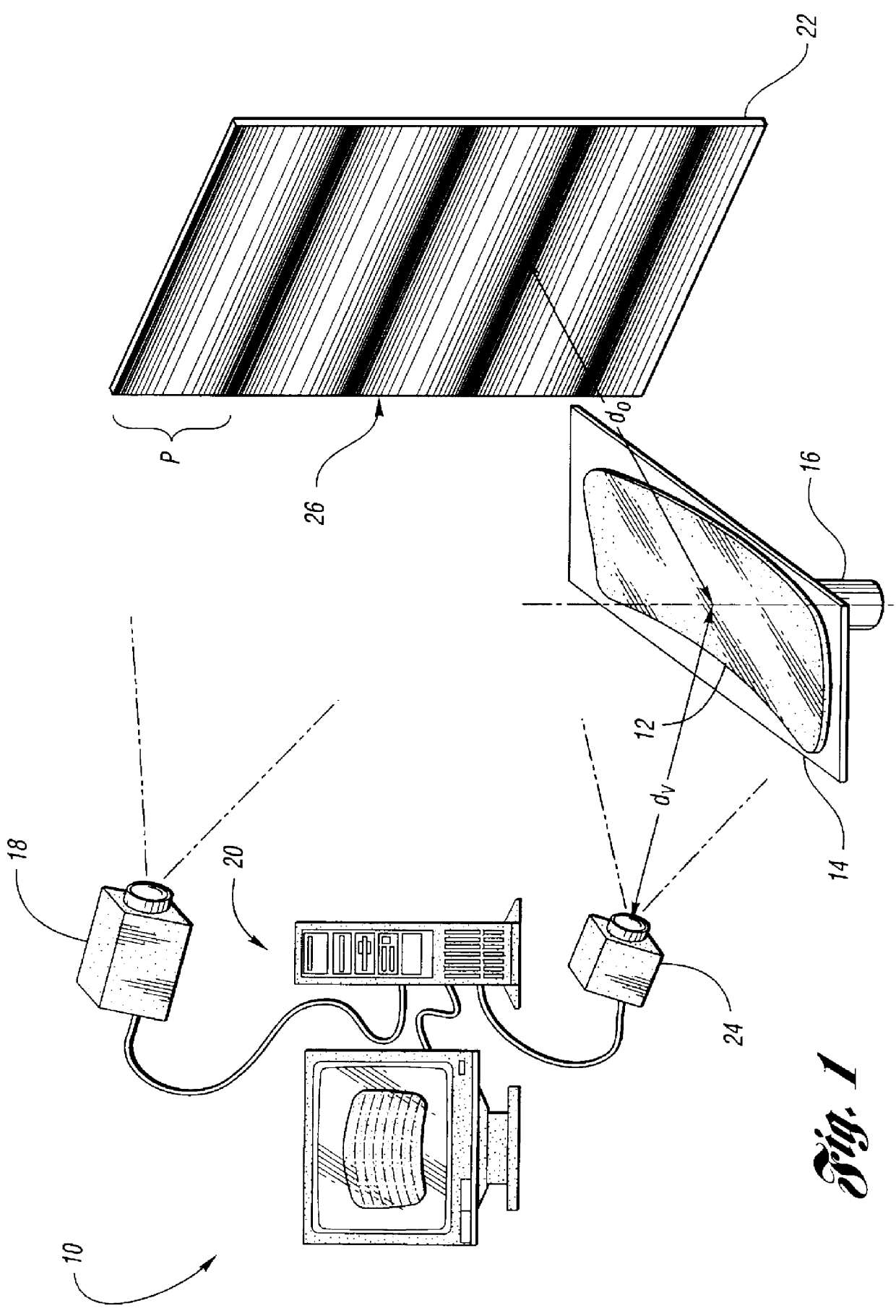
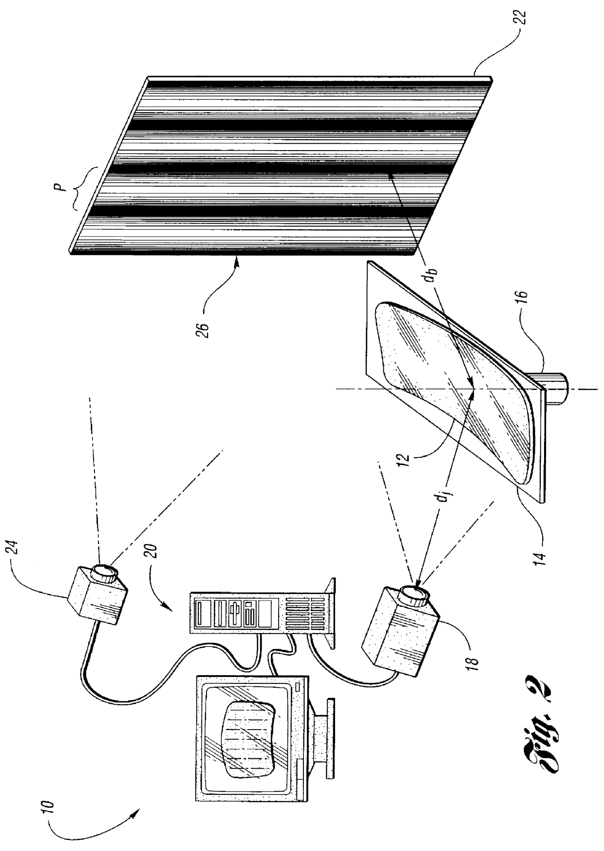
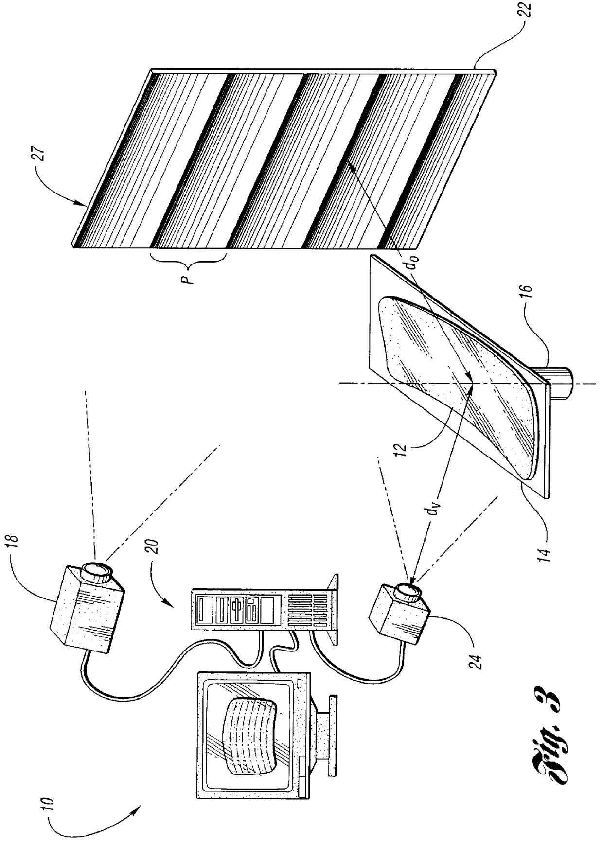
FIG. 1 shows an apparatus 10 according to the invention for determining reflective optical quality of a reflective product, such as a front windshield 12 for a motor vehicle. Other exemplary reflective products include mirrors, windows and any other shiny, relatively smooth object. The windshield 12 is supported on a generally flat surface 14 of an optionally rotatable work table 16.

As shown in FIG. 1, the apparatus 10 includes a projector 18 in communication with a computer 20. The projector 18 is used to project one or more gray-scale targets or patterns onto a reference plane, such as a screen 22, which is located behind the windshield 12 at a distance do from the windshield 12. Gray-scale pattern as used herein refers to a pattern having a varying light intensity, such as sinusoidal grating or sawtooth grating, and the pattern has a well defined phase at each point that is coded by intensity. Advantageously, the projector 18 and computer 20 can be used to quickly generate and pr...


PUM

PropertyMeasurementUnit
horizontal distanceaaaaaaaaaa
reflective optical qualityaaaaaaaaaa
optical qualityaaaaaaaaaa

Abstract

A method of determining reflective optical quality of a reflective product includes reflecting a first gray-scale pattern off the product; obtaining a first image of the first pattern with an image pickup device after the first pattern has reflected off of the product; and determining optical quality of the product based on data obtained from the first image. An apparatus for determining reflective optical quality of such a product is also disclosed.

Description

The invention relates to an apparatus and method for determining reflective optical quality of a reflective product using one or more gray-scale patterns, wherein the one or more patterns are reflected off of the product.A prior method for determining reflective optical quality of a reflective product, such as a front windshield for a motor vehicle, involves reflecting a point light source off of the product and onto a white screen. A camera is then used to measure intensity variations of the light as seen on the screen. This method, however, is subject to errors if reflective properties of the product are not uniform. For example, if the product has a surface coating with variations in thickness, such variations are interpreted as variations in optical power.DISCLOSURE OF INVENTIONThe invention overcomes the shortcomings of the prior art by providing a method and apparatus for determining reflective optical quality of a reflective product at any and all points on the product. Furth...

Claims


Application Information

Patent Timeline
Patent Type & Authority Patents(United States)
IPC IPC(8): G01N21/55G01M11/00
CPCG01N21/55G01N21/958G01N21/8806
Inventor LADEWSKI, THEODORE B.
Owner FORD GLOBAL TECH LLC
Why Eureka
Try Eureka