Quantitative analyte detection in lateral flow immunochemistry

a technology of immunochemistry and quantitative analyte, applied in the direction of instruments, measurement devices, color/spectral property measurement, etc., can solve the problems of inconvenient reading, high cost, limited technique, etc., and achieve accurate and repeatable results.

Pending Publication Date: 2021-03-04
ARONOWITZ MIREYA C
View PDF2 Cites 1 Cited by
  • Summary
  • Abstract
  • Description
  • Claims
  • Application Information

AI Technical Summary

Benefits of technology

[0005]Embodiments of the subject invention provide novel and lateral flow immunochemistry testing systems and methods that address the disadvantages and limitations of related art systems and methods. A system can include a tester substrate with at least two control (known-value) zones that can each produce a control indicator line corresponding to a known value of an analyte, one having a lower known value than the other. The analyte can be conjugated to marker that can be measured with a measuring device. There can also be at least one test sample zone that can produce a test sample line when contacted with the conjugated-analyte in the test sample. A test sample with an unknown amount of conjugated-analyte can be deposited on a tester substrate, such as, for example, in a sample well that is in contact with the tester substrate. The test sample can migrate by capillary action, through the tester substrate, until it reaches the at least two control zones and the at least one test sample zone, whereby at least two control lines are created and at least one test sample line is created. A reader, meter, or other measuring device can be used to compare the at least one test sample line to the at least two known-value control lines, which are used as or can provide a standard against which to compare the test sample line to quantify the amount of analyte present in the test sample. The embodiments of the systems and methods of the subject invention are inexpensive and provide accurate and repeatable results.

Problems solved by technology

Because of the limitations of the chromatography, flow, and materials, this technique is limited in the related art to reporting simply the presence or absence of a protein or other analyte.
With the improvements in camera technology, readers based on pixel and / or camera technology have been developed, but such readers are extremely inconsistent and expensive.

Method used


Image

  • Quantitative analyte detection in lateral flow immunochemistry
  • Quantitative analyte detection in lateral flow immunochemistry
  • Quantitative analyte detection in lateral flow immunochemistry

Examples


embodiment 1

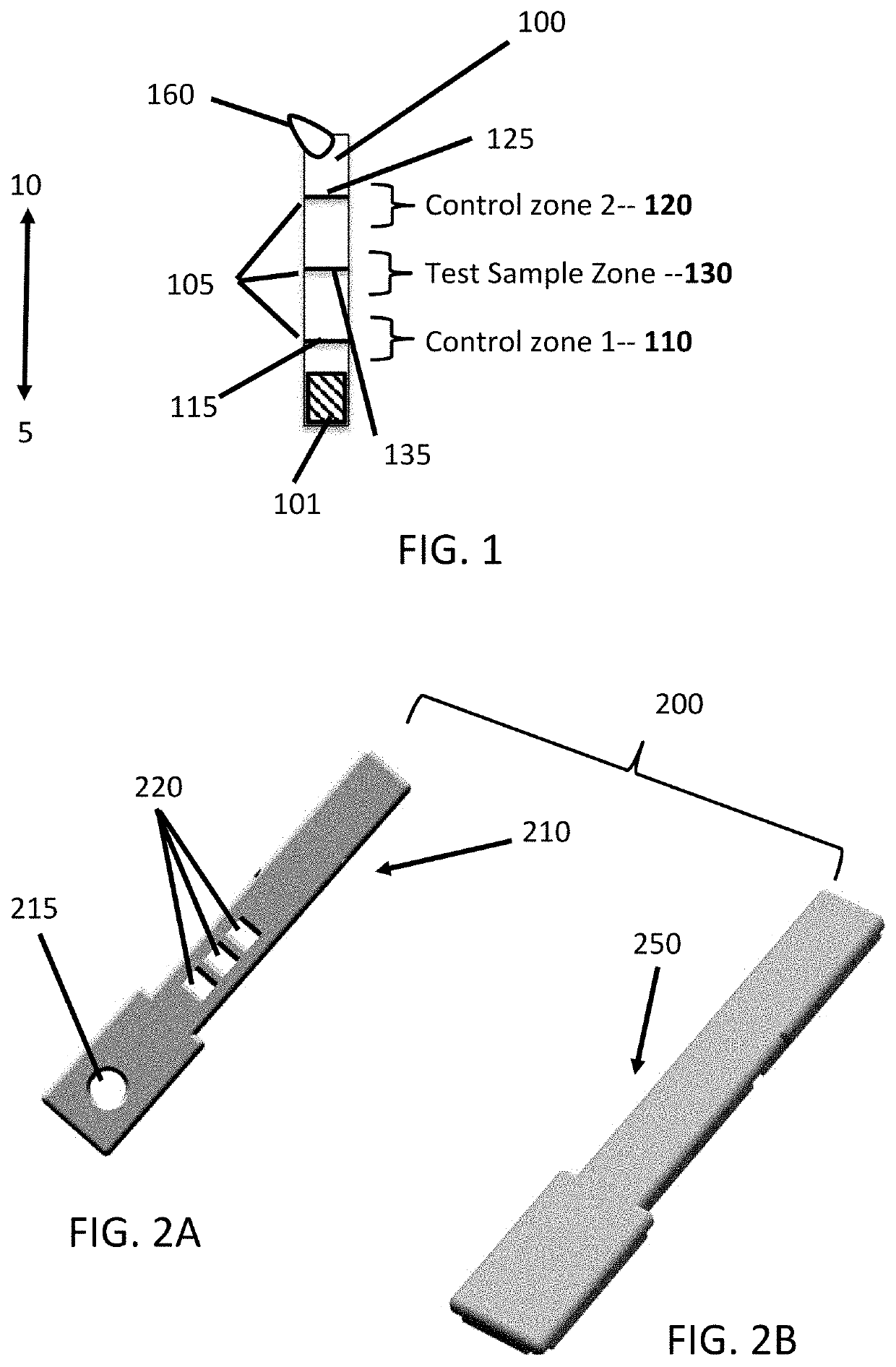
[0042]A tester substrate, configured to obtain a quantitative amount of an analyte in a test sample, the tester substrate comprising:

[0043]at least one test sample zone comprising a moiety-binding substance that binds to a moiety that is the analyte or is bound to the analyte; and

[0044]at least two control zones, each control zone comprising a known different amount of the moiety-binding substance, and configured such that when contacted with the analyte in the test sample, binds with a corresponding known amount of the moiety in the test sample, such that obtaining a measure of the amount of moiety bound to each control zone provides standards against which a measure obtained for the amount of moiety bound to the test sample zone can be compared to determine a quantitative amount of the analyte in the test sample.

embodiment 2

[0045]The tester substrate according to embodiment 1, wherein the moiety is conjugated to a visual, magnetic, or fluorescent marker that causes a test sample line to be formed when the moiety binds to the at the at least one test sample zone and causes a control line to be formed in each of the at least two control zones.

embodiment 3

[0046]The tester substrate according to any of embodiments 1-2, wherein the line is measured to obtain the quantitative amount for the analyte bound at each of the at least one test zone and the at least two control zones.


PUM

PropertyMeasurementUnit
magneticaaaaaaaaaa
fluorescentaaaaaaaaaa
dimensionsaaaaaaaaaa

Abstract

Lateral flow immunochemistry testing systems and methods are provided. A system can include a tester substrate with at least two control lines and at least one test sample line. A test sample with an unknown amount of analyte can be deposited on the tester substrate and the test sample can move along the tester substrate, to contact the at least two control lines and the at least one test sample line. A measuring device can be used to compare the at least one test sample line to the at least two control lines to give a quantitative value of the amount of analyte present in the test sample.

Description

CROSS-REFERENCE TO A RELATED APPLICATION[0001]This application claims the benefit of U.S. Provisional Application Ser. No. 62 / 893,235, filed Aug. 29, 2019, which is hereby incorporated by reference herein in its entirety, including any figures, tables, and drawings.BACKGROUND[0002]Lateral flow immunochemistry has been around for almost 40 years and is widely used for both point of care testing, rapid testing at home, and in clinical environments. One of the first practical uses was the one-step pregnancy test (see, e.g., U.S. Pat. No. 4,774,192). Because of the limitations of the chromatography, flow, and materials, this technique is limited in the related art to reporting simply the presence or absence of a protein or other analyte. When visually read, the best that can be done is comparison to a control line (e.g., luteinizing hormone (LH)) to determine if the sample appears stronger or weaker than the control line. With the improvements in camera technology, readers based on pixe...

Claims


Application Information

Patent Timeline
Patent Type & Authority Applications(United States)
IPC IPC(8): G01N33/543
CPCG01N33/54386G01N33/54388G01N21/78G01N21/31
Inventor ARONOWITZ, JACK L.
Owner ARONOWITZ MIREYA C
Why Eureka
Try Eureka