Assembly structure for rack and rubber roll as well as thermal printer applying assembly structure

A technology for thermal printers and assembly structures, applied in printing devices, printing, etc., can solve the problems of affecting the normal operation of rubber rollers, large bearing movement, and increasing manufacturing costs, so as to ensure normal and stable operation, low cost, and zero cost. The effect of easy access to parts

Inactive Publication Date: 2012-05-02
宁波精芯科技有限公司
View PDF5 Cites 3 Cited by
  • Summary
  • Abstract
  • Description
  • Claims
  • Application Information

AI Technical Summary

Problems solved by technology

But there are the following disadvantages: the bearing moves in the groove to a large extent, which affects the normal operation of the rubber roller
The operation is simple, and the positioning is ready and the operation is smooth, but the overall structure of the structure is relatively complicated, and the door-opening tablet is an unconventional component, which increases the difficulty of the process and increases the manufacturing cost

Method used


Image

  • Assembly structure for rack and rubber roll as well as thermal printer applying assembly structure
  • Assembly structure for rack and rubber roll as well as thermal printer applying assembly structure
  • Assembly structure for rack and rubber roll as well as thermal printer applying assembly structure

Examples


Embodiment Construction

[0022] The present invention will be further described in detail below in conjunction with the accompanying drawings and embodiments.

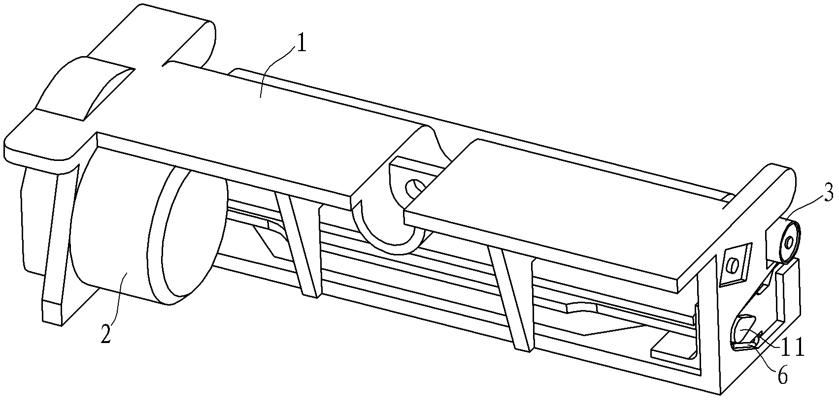
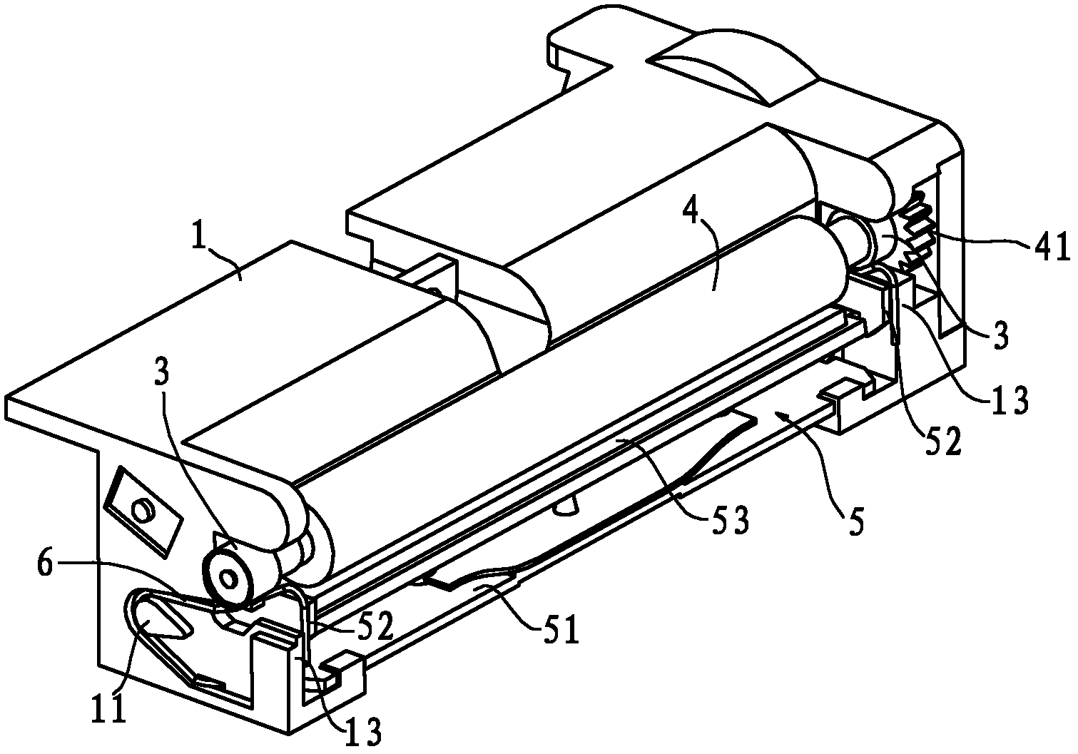
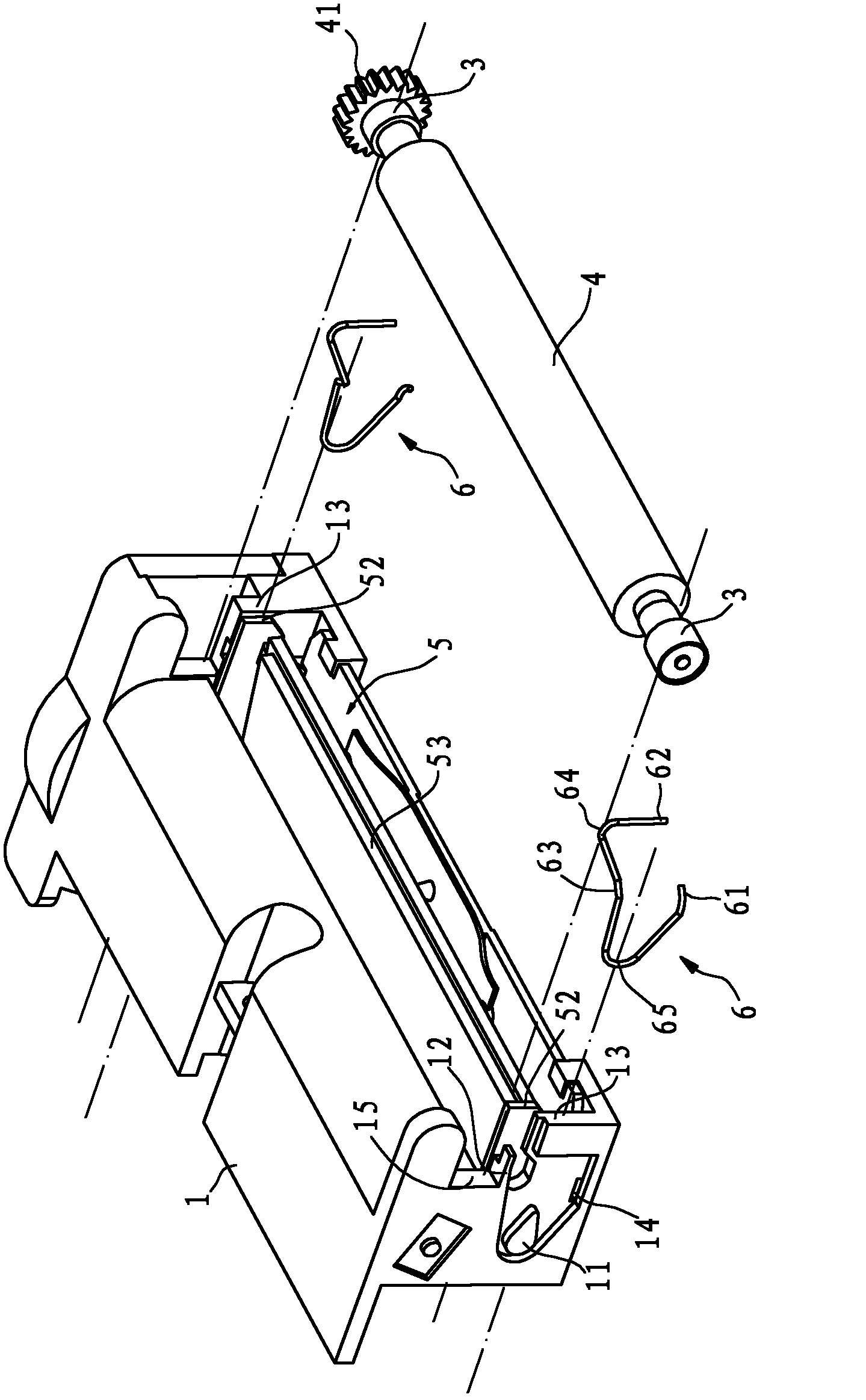
[0023] Such as figure 1 , figure 2 and image 3 As shown, the thermal printer in this embodiment includes a main frame 1 and a motor 2 arranged on the main frame 1, a transmission gear assembly (not shown in the figure), a print head assembly 5 and a rubber roller 4, and the power of the transmission gear assembly The input end meshes with the active output gear of the motor 1, and the power output end meshes with the rubber roller gear 41 located at the end of the rubber roller 4. The main frame 1 has a central area, and side walls 13 are formed on both sides of the central area. The printer head assembly 5 includes a bracket 51 disposed in the central area and a print head 53 disposed on the bracket 51 , and side portions 52 are formed on both sides of the bracket 51 .

[0024] There are two bearings 3 at both ends of the rubber roller 4...


PUM


Abstract

An assembly structure for a rack and a rubber roll comprises a primary rack and the rubber roll rotatably arranged on the primary rack, two bearings are arranged at both ends of the rubber roll, and the primary rack is provided with grooves in which the bearings are arranged. The assembly structure is characterized in that: snap springs enclosed by metal wires are arranged on the primary rack, each snap spring is provided with an elastic limit part which is projected out of the port of each groove, and the bearings are limited in the areas formed by the elastic limit parts and the grooves. The invention also discloses a thermal printer applying the assembly structure. Compared with the prior art, the assembly structure and the thermal printer have the advantages that: the whole body is simple and quick to assemble without special requirement on the grooves, the bearings almost cannot bounce under the action of the elastic limit parts, and thereby the normal stable operation of the rubber roll is guaranteed.

Description

technical field [0001] The invention relates to an assembly structure of a thermal printer frame and rubber rollers, and also relates to a thermal printer using the assembly structure. Background technique [0002] Existing thermal printers generally include a main frame, a motor, a transmission gear assembly, a print head assembly, and a rubber roller that can be rotatably arranged on the main frame. The power input end of the transmission gear assembly meshes with the active output gear of the motor, and the power The output end meshes with the rubber roller gear located at the end of the rubber roller. The rubber roller is used to drive the printing paper to move. There is a paper feeding channel between the rubber roller and the print head assembly. There are two bearings at both ends of the rubber roller. On the main frame Has grooves for bearing placement. Typically, the grooves are semicircular in shape. This design basically meets the requirements for bearing assem...

Claims


Application Information

Patent Timeline
Patent Type & Authority Applications(China)
IPC IPC(8): B41J11/00B41J2/32
Inventor 蒋文柏
Owner 宁波精芯科技有限公司
Why Eureka
Try Eureka