Method of determining use priority of various control surfaces of multi-control surface plane at close-range stage

A multi-control surface and control surface technology, applied in the field of flight control, can solve problems affecting aircraft, slow response of aircraft control, and affecting aircraft flight performance, so as to reduce adverse costs and improve flight performance.

Inactive Publication Date: 2013-08-28
NORTHWESTERN POLYTECHNICAL UNIV
View PDF3 Cites 0 Cited by
  • Summary
  • Abstract
  • Description
  • Claims
  • Application Information

AI Technical Summary

Problems solved by technology

The aircraft with multiple control surfaces can use various control methods to meet the control requirements, but the cost of different control methods is also different. This is mainly because, firstly, the deflection of the control surfaces can not only generate the control moment, but also affect the lift-drag characteristics of the aircraft. If the control method that affects the lift-drag characteristics of the aircraft is selected, it will affect the flight performance of the aircraft; secondly, the deflection angle and deflection rate of the steering gear on the control surface are limited, so the control surface The generated control torque is limited, and it will take a certain amount of time to reach the desired control torque. If too many control surfaces with low steering gear deflection rate are selected, although the desired control torque can still be achieved in the end, the control response of the aircraft will be affected. Slower, which affects the agility of the aircraft

Method used


Image

  • Method of determining use priority of various control surfaces of multi-control surface plane at close-range stage
  • Method of determining use priority of various control surfaces of multi-control surface plane at close-range stage
  • Method of determining use priority of various control surfaces of multi-control surface plane at close-range stage

Examples


Embodiment

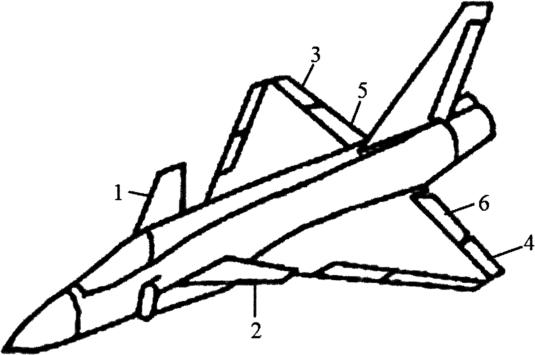
[0018] With reference to accompanying drawing 1, adopt the method of the present invention to determine the use priority of each control surface of certain type multi-control surface aircraft in close-range air combat stage in the present embodiment. In the embodiment, the control surfaces suitable for use by the multi-control surface aircraft in the short-range air combat stage include: the right close-coupled canard 1, the left close-coupled canard 2, the right outer elevon 3, and the left outer elevon 4 , the right inner elevon 5, the left inner elevon 6 and the rudder, wherein since the rudder is the only heading control surface, it is not necessary to determine its deflection angle through the control allocation process, so it is necessary to determine the use priority in this embodiment The control surfaces are the right near-coupled canard 1, the left near-coupled canard 2, the right outer elevon 3, the left outer elevon 4, the right inner elevon 5 and the left inner ele...


PUM


Abstract

The invention provides a method of determining a use priority of various control surfaces of a multi-control surface plane at a close-range stage. The method adopts the equation of J delta i=aLD[(L / D) delta i-(L / D)0] +amRm delta i+arlRrl delta i to determine the use priority of various control surfaces at the flight condition of the same mach number and angle of incidence, wherein delta Cm delta i is the pitching control efficacy of the ith control surface; CL0 and CD0 are lift coefficient and resistance coefficient in case of deflection of the plane without the control surface; delta CL delta i and delta CD delta i are additional lift coefficient and additional resistance coefficient after the ith control surface deflects the unit angle; RL delta i is the deflection rate of the ith control surface; and RL delta 0 is the deflection rate of the reference control surface. The method meets the requirements of lift and resistance characteristics, control surface efficacy and deflection capability of a steering engine of the plane at the close-range air war stage, and determines the use priority of various control surfaces of the plane based on the requirements, the control surface with high priority can be selected to use at multiple control ways, the unfavorable cost in the control process is lowered, and the flight performance of the plane at the close-range air war stage is improved.

Description

technical field [0001] The invention relates to the field of flight control, in particular to a method for determining the use priority of each control surface of an aircraft with multiple control surfaces in the short-distance stage. Background technique [0002] The three control surfaces of the traditional layout aircraft, including the elevator, aileron and rudder, respectively correspond to the attitude control in the three directions of pitch, roll and yaw. The number of control surfaces is equal to the number of control expected parameters, and the control method is unique. In order to meet the expected performance requirements, modern new aircraft generally introduce some new control surfaces. For example, in order to obtain maneuverability at high angle of attack, a close-coupled canard is introduced; in order to obtain post-stall maneuverability and maneuverability, thrust vectoring is introduced; in order to improve takeoff and landing performance, a lift device i...

Claims


Application Information

Patent Timeline
Patent Type & Authority Patents(China)
IPC IPC(8): B64D31/06
Inventor 刘艳高正红颜世伟豆国辉
Owner NORTHWESTERN POLYTECHNICAL UNIV
Why Eureka
Try Eureka