Halo orbit detector structure of sun-earth system and attitude directing thereof

A technology for detectors and orbits, which is applied in the field of configuration and attitude pointing of Halo orbit detectors of the sun-earth system, which can solve problems such as difficult control, many rotating parts of the detector, and great flexibility, and achieve the effect of reducing weight

Active Publication Date: 2012-05-02
BEIHANG UNIV
View PDF5 Cites 18 Cited by
  • Summary
  • Abstract
  • Description
  • Claims
  • Application Information

AI Technical Summary

Problems solved by technology

As a result, the detector has many rotating pa

Method used


Image

  • Halo orbit detector structure of sun-earth system and attitude directing thereof
  • Halo orbit detector structure of sun-earth system and attitude directing thereof
  • Halo orbit detector structure of sun-earth system and attitude directing thereof

Examples


Embodiment Construction

[0032] The present invention will be further described in detail below in conjunction with the accompanying drawings.

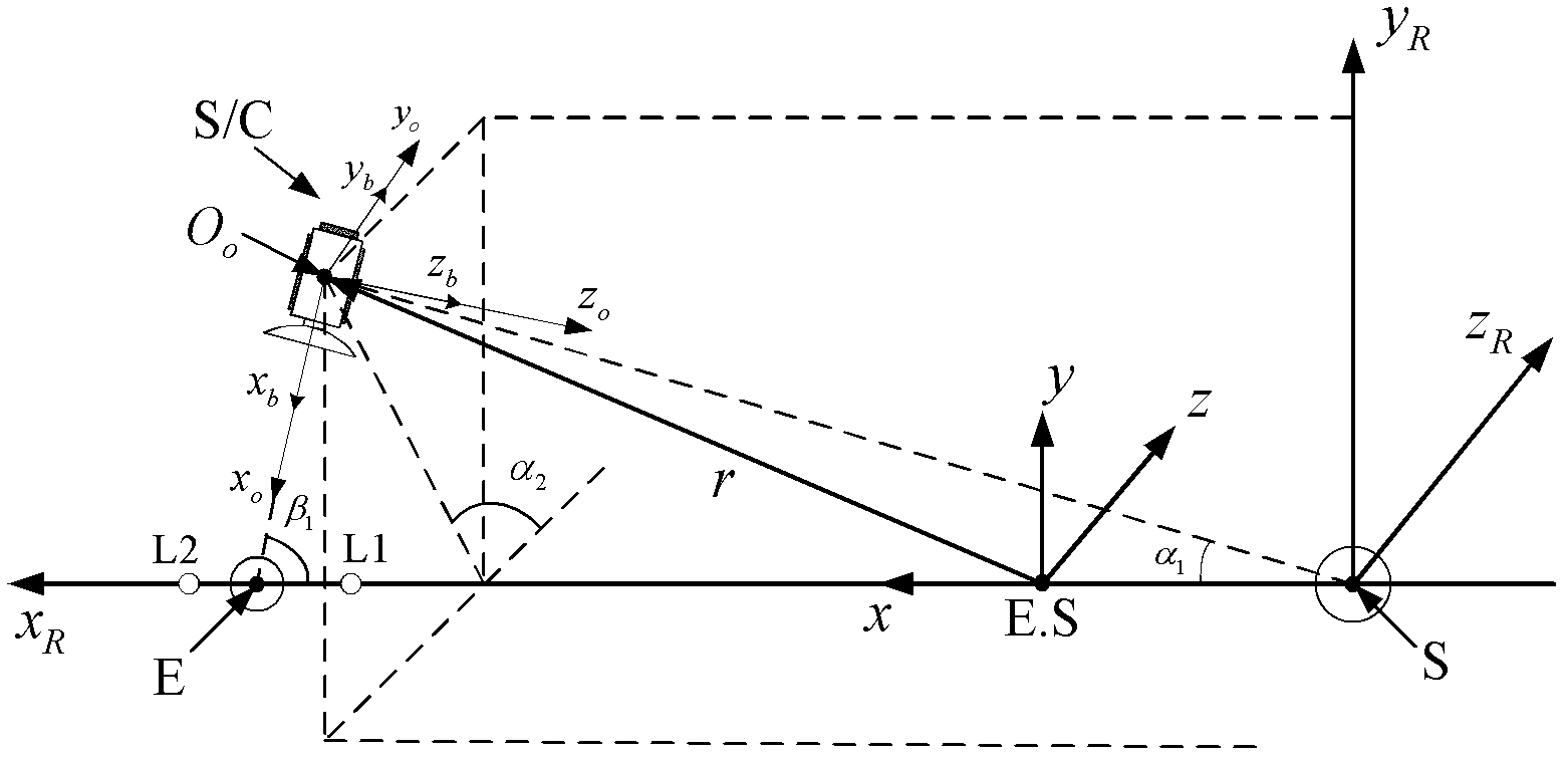
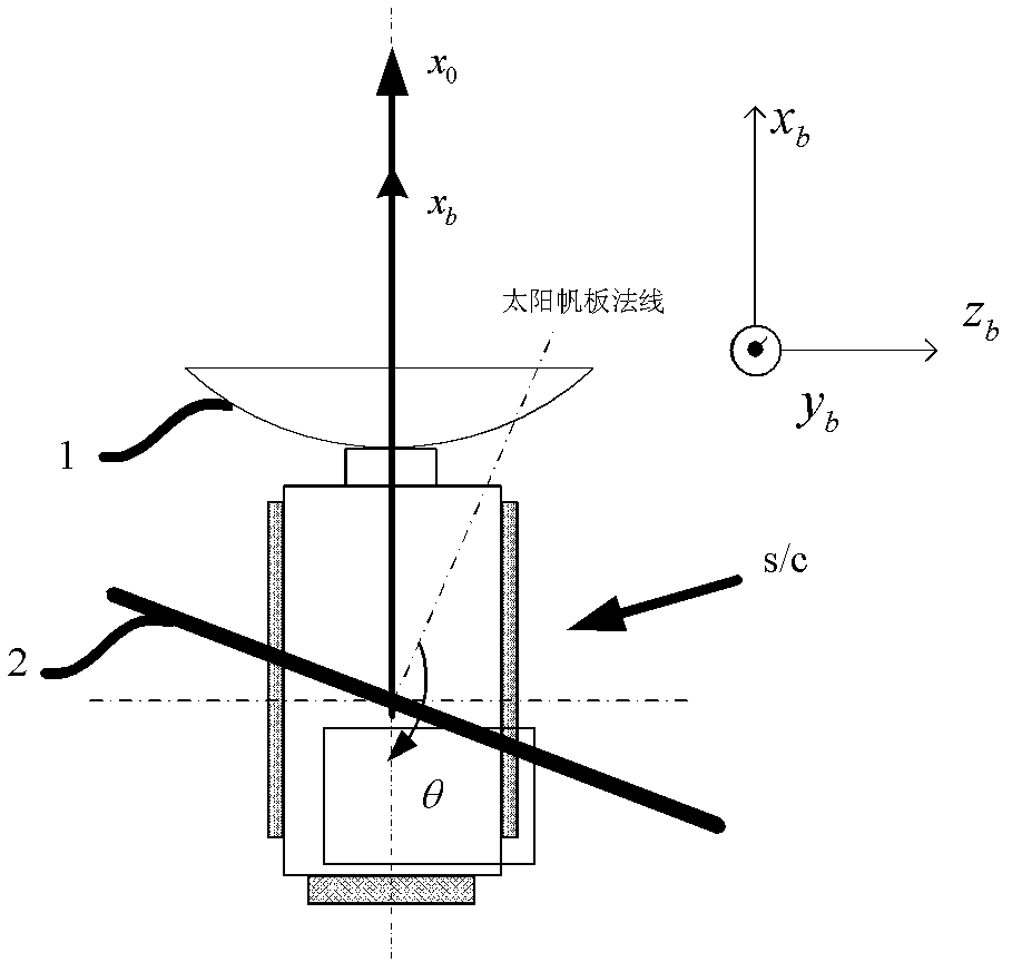
[0033]The configuration and attitude orientation of a sun-earth system Halo orbit detector of the present invention, such as figure 1 , figure 2 As shown, define detector 1 orbital coordinate system FO(x o the y o z o ), where the center of mass of the detector S / C is taken as the origin O O , x o axis pointing towards the earth, y o It is perpendicular to the plane formed by the sun, the probe S / C and the earth, pointing to the direction of the velocity vector of the probe S / C in the direction of an acute angle, z o Satisfy Cartesian right-hand rule. Define the detector S / C body coordinate system FB(x b the y b z b ), which is obtained by using the rotation order of 3-1-2 relative to the orbital coordinate system of the detector S / C, +x b , +y b , +z b represent x respectively b ,y b ,z b The positive direction of the axis, -x b ,-y b ...


PUM


Abstract

The invention discloses a halo orbit detector structure of a sun-earth system and an attitude directing thereof, belonging to the design field of spacecrafts. A digital antenna is fixedly arranged on the +xb surface of a detector body; a shaft of the digital antenna is along the xb shaft direction; solar arrays are fixedly arranged on the +/-yb surface of the detector, the axial line is vertical to the +/-yb surface of the detector body, and the included angle between the normal and the -xb shaft is theta which is the installation angle of the solar array and is calculated by average halo orbit information. The xb shaft of the detector body is directional to the ground during the running time of the detector. The normal of the solar array directs to the sun, after the theta is selected, the solar incident angle of the solar array changes within a certain range and is 90 degrees on average in the orbit cycle. The halo orbit detector structure has the advantages that the long-term direction of the digital antenna to the ground is realized by means of one fixed digital antenna and one pair of fixed solar arrays, the solar arrays are directional to the sun for a long term through the digital antenna with low digital code rate, moving parts of the detector are few, the controllability and reliability of the detector are greatly improved, and the control difficulty is reduced.

Description

technical field [0001] The invention relates to the field of spacecraft design, in particular to the configuration and attitude orientation of a sun-earth system Halo orbiter. Background technique [0002] At present, the tentacles of human deep space exploration activities have been extended from the moon to terrestrial inner planets (including Mercury, Venus) and terrestrial outer planets (including Mars, Jupiter). Exploration missions include global earth map surveys, environmental and geological scientific explorations. The Sun-Earth Lagrangian point L1 / L2 point Halo orbit is located on the inner side and outer side of the earth respectively. [0003] A number of spacecraft positioned around Lagrange points have been launched internationally. [0004] ISEE-3 / ICE was launched on August 12, 1978, with a mass of 478kg and a lifespan of 32 years. It is located at the L1 point of the sun and the earth, and has a Halo orbital period of 178 days. It is used for comet detectio...

Claims


Application Information

Patent Timeline
IPC IPC(8): B64G1/24
Inventor 徐明朱佳敏谭田张燕杨芳徐世杰
Owner BEIHANG UNIV
Why Eureka
Try Eureka