Supercharge Your Innovation With Domain-Expert AI Agents!

Hydraulic dual-high-driving pulling and discharging type fluid pump

A fluid pump and hydraulic technology, which is applied in the field of hydraulic double-height submerged pull-discharge type fluid pumps, can solve the problems of intermittent drainage, cumbersome use and operation, running and ignition, etc., and achieves convenient use, convenient operation, and improved work. The effect of efficiency

Inactive Publication Date: 2012-05-02
周凯
View PDF7 Cites 0 Cited by
  • Summary
  • Abstract
  • Description
  • Claims
  • Application Information

AI Technical Summary

Problems solved by technology

However, when the explosion-proof motor of the water pump is submerged in water, it cannot work normally, which can cause the entire drainage system to be paralyzed; because the underground environment is relatively harsh, the power supply line is also prone to phenomena such as exposure, leakage, and ignition during operation, resulting in gas failure in the underground mine. High areas lead to gas explosions, increase underground safety hazards, and bring great difficulties to disaster relief work
[0004] In order to meet the requirements of working conditions, the submersible pumps used in large mines must use relatively large power pumps to meet the required flow and head. However, the existing impeller pumps or turbo pumps are large in size and heavy in weight. It takes a long time to install and use, and consumes huge resources, materials and manpower. The use and operation are cumbersome, and it is not easy to be flexible. In addition, although the existing piston pump can meet the head requirements, the displacement is small, the drainage is intermittent, and the efficiency is low.

Method used


Image

  • Hydraulic dual-high-driving pulling and discharging type fluid pump
  • Hydraulic dual-high-driving pulling and discharging type fluid pump

Examples


Embodiment Construction

[0015] The hydraulic double-high submerged pull-and-discharge fluid pump of the present invention will be further described in detail below in conjunction with the accompanying drawings.

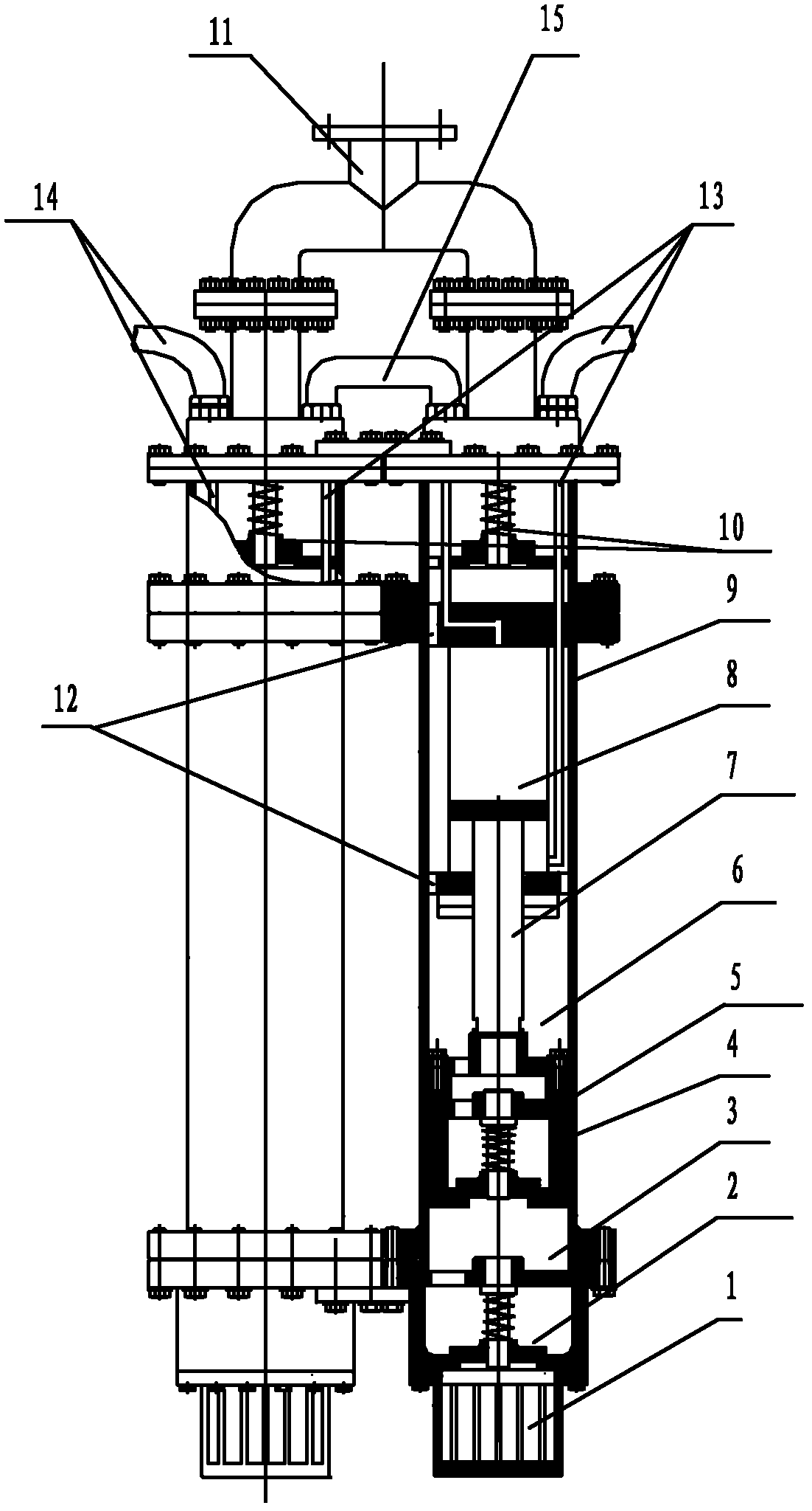
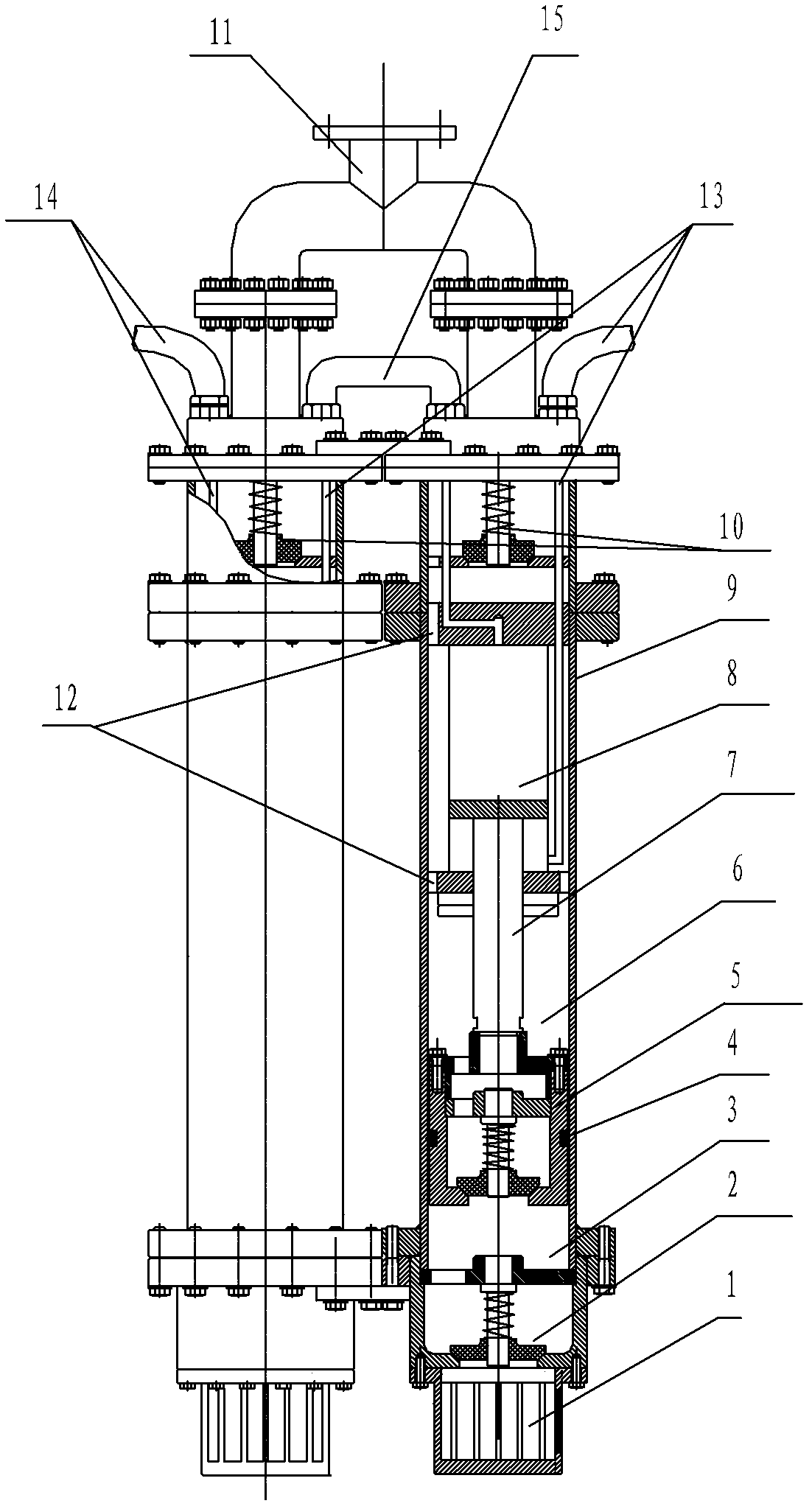
[0016] as attached figure 1 As shown, the hydraulic double-high submerged pulling-type fluid pump of the present invention includes a hydraulic station and two pulling-type fluid pumps, the pulling-type fluid pump includes a cylinder 9, and the oil outlet pipe of the first cylinder oil cylinder It communicates with the oil inlet pipe of the second cylinder oil cylinder through a connecting pipe. The water inlet check valve 2, the piston check valve 5, the drain check valve 10 and the oil cylinder 8 are arranged in the cylinder barrel 9. A first cavity 3 and a second cavity 6 communicating with each other are provided, the first cavity 3 communicates with the water inlet through the water inlet check valve 2, and the second cavity 6 communicates with the water inlet through the piston check v...


PUM


Abstract

The invention discloses a hydraulic dual-high-driving pulling and discharging type fluid pump which comprises a hydraulic station and two pulling and discharging fluid pumps, wherein each pulling and discharging fluid pump comprises a cylinder barrel, one end of the cylinder barrel is provided with a water inlet, the other end of the cylinder barrel is provided with a water outlet; the cylinder barrel is internally provided with a water inlet check valve, a first cavity, a piston check valve, a second cavity, an oil cylinder and a water outlet check valve sequentially from the water inlet to the water outlet; and the water outlets of the two pulling and discharging fluid pumps are communicated through a water outlet three-way pipe, and the oil cylinders of the two pulling and discharging fluid pumps are serially communicated through a connecting pipe. The invention has the advantages of electromechanical separation, high lift, high efficiency, and realization of continuous water drainage, and the like, and is suitable for production water drainage in fields of coal mines, non-coal mines, and the like, is especially suitable for carrying out emergency rescue water drainage and water drainage complex ore on water burst accidents in a process of mine exploitation, and provides strong measures and guarantees for safety production and emergency rescue and disaster relief of mines.

Description

Technical field: [0001] The invention relates to a fluid pump, in particular to a hydraulic double-high submerged pull-out fluid pump. Background technique: [0002] With the rapid development of society, safety production and technical equipment are getting more and more attention from all over the world. my country is rich in mineral resources, most of which are mined in mines, while the underground environment is complex and changeable, and is often threatened by natural disasters such as gas, water, and fire, which seriously endanger the lives of underground miners. Disaster capability is weak, and mining accidents occur frequently. Therefore, it is imperative to strengthen the safety production conditions and technical equipment transformation of mining enterprises to eliminate potential safety hazards. [0003] Explosion-proof motor-driven water pumps are usually used as drainage equipment for mine drainage, emergency rescue and disaster relief, and drainage and mine r...

Claims


Application Information

Patent Timeline
IPC IPC(8): F04B9/113
Inventor 周凯
Owner 周凯
Features
  • R&D
  • Intellectual Property
  • Life Sciences
  • Materials
  • Tech Scout
  • Unparalleled Data Quality
  • Higher Quality Content
  • 60% Fewer Hallucinations
Learn More