A high-speed rotor and a control moment gyroscope using the rotor

A high-speed rotor and housing technology, applied in the direction of rotating gyroscope, etc., can solve the problem of narrow temperature range, and achieve the effect of solving the narrow temperature range and ensuring stability

Active Publication Date: 2015-10-21
LUOYANG BEARING RES INST CO LTD
View PDF10 Cites 0 Cited by
  • Summary
  • Abstract
  • Description
  • Claims
  • Application Information

AI Technical Summary

Problems solved by technology

[0003] The purpose of the present invention is to provide a high-speed rotor to solve the problem that the high-speed rotor of the existing control torque gyroscope has a narrow temperature range; at the same time, the purpose of the present invention is also to provide a control torque gyroscope using the above-mentioned high-speed rotor

Method used


Image

  • A high-speed rotor and a control moment gyroscope using the rotor
  • A high-speed rotor and a control moment gyroscope using the rotor
  • A high-speed rotor and a control moment gyroscope using the rotor

Examples


Embodiment Construction

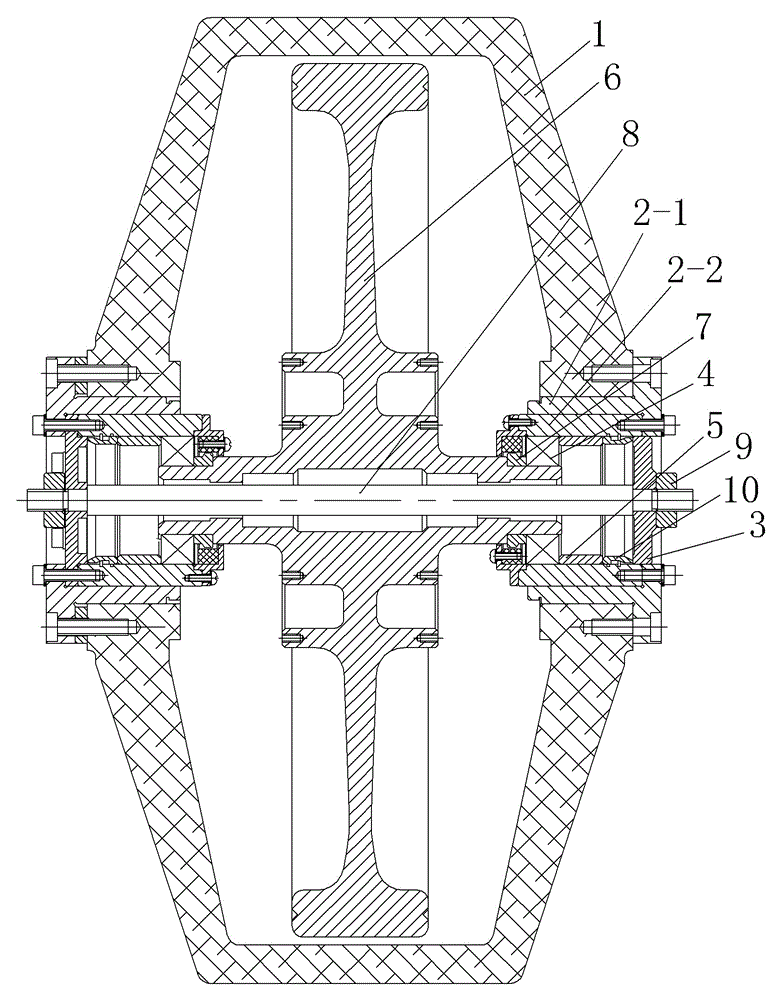
[0014] Example 1 of a high-speed rotor, such as figure 1 As shown, there is a housing 1, the housing 1 is equipped with bearing seats on opposite sides respectively, and the two bearing seats are connected to the outer cylinder 2-1 on the housing by flanges and coaxially fixedly assembled on the outer cylinder 2- 1 is composed of a core tube 2-2, and the outer ends of the core tubes 2-2 of each bearing seat are connected with the inversion edge bolts at the outer end of the outer tube; the two bearing seats are respectively provided with bearing glands 3 at the outer ends, Angular contact ball bearings 4 are installed inside, and the two angular contact ball bearings 4 located in the two bearing seats are arranged opposite to each other. The respective outer rings of the two angular contact ball bearings 4 respectively pass through the loading rings arranged between them and the corresponding bearing glands. 5 and the disc spring 10 are tightened so that the two angular contac...


PUM


Abstract

The invention relates to a high-speed rotor and a control moment gyro using the same. The high-speed rotor comprises a shell and a wheel body arranged in the shell, wherein the wheel body is rotatably assembled on the shell by utilizing two angular contact ball bearings as a support; bearing covers are respectively arranged at the axial outer sides of the two angular contact ball bearings; a drawbar penetrates through the wheel body coaxially and rotatably; the two bearing covers are respectively fixedly assembled on corresponding ends of the drawbar; and one of the bearing covers is in stationary fit with the shell, and the other one of the bearing covers is in pilot clearance fit with the shell along the axial direction of the wheel body. When the temperature in the working environment of the control moment gyro rises or falls, the cover in pilot fit with the shell can compensate for the difference of linear expansion values between the shell and the wheel body through the movement relative to the shell, thus the stability of the anticipated load of the two angular contact ball bearings can be ensured, and further the control moment gyro can be adapted to working environments with a relatively wide range of temperature difference, therefore the problem of a narrow range of applicable temperature of the high-speed rotor of the existing control moment gyro is solved.

Description

technical field [0001] The invention relates to the technical field of bearings, in particular to a high-speed rotor and a control moment gyroscope using the rotor. Background technique [0002] The control moment gyroscope is a widely used actuator in the attitude control system in the aerospace field, and the high-speed rotor is the core rotating part of the control moment gyroscope. The high-speed rotor casing and the wheel body inside the casing, wherein the wheel body is rotatably assembled on the high-speed rotor casing through a pair of angular contact ball bearings as a rotating support during operation, and is fixedly mounted on the high-speed rotor casing through the loading ring and The bearing gland on the casing applies axial positioning preload to the two angular contact ball bearings, thereby ensuring the shafting of the high-speed rotor has appropriate rigidity, thereby ensuring the smooth operation of the high-speed rotor. Wherein the wheel body needs to ro...

Claims


Application Information

Patent Timeline
Patent Type & Authority Patents(China)
IPC IPC(8): G01C19/06G01C19/16
Inventor 杨虎高飞郭向东靳国栋姜维尚修鑫
Owner LUOYANG BEARING RES INST CO LTD
Why Eureka
Try Eureka