
Thermal vibration joint test device and method of flange sealing structure under complicated loaded conditions

A technology of flange sealing and test method, which is applied in the field of heat-shock combined sealing test device, and can solve the problems of no test method report and so on

Active Publication Date: 2013-11-06
AEROSPACE RES INST OF MATERIAL & PROCESSING TECH +1
View PDF6 Cites 0 Cited by
  • Summary
  • Abstract
  • Description
  • Claims
  • Application Information

AI Technical Summary

Problems solved by technology

Check the prior art literature, there is no relevant test method report

Method used


Image

  • Thermal vibration joint test device and method of flange sealing structure under complicated loaded conditions
  • Thermal vibration joint test device and method of flange sealing structure under complicated loaded conditions
  • Thermal vibration joint test device and method of flange sealing structure under complicated loaded conditions

Examples


Embodiment 1

[0029] Assess the heat-shock joint test of the flange sealing structure at 330°C, applying a flange axial force of 15000N (allowable deviation 20%) and a flange lateral force of 4000N (allowable deviation 20%), and a sealing pressure of 0.95MPa.

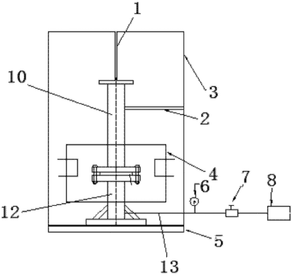
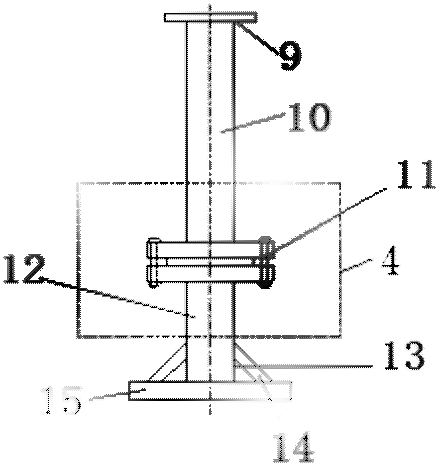
[0030] The structure of the test device is as figure 1 with figure 2 shown. The device includes a force-applying pipe section 10 with a flange at the lower end and a load-bearing pipe section 12 with a flange at the upper end. The flange sealing structure to be tested is placed on the flange plate and the load-bearing pipe section 12 of the force-applying pipe section 10 arranged up and down. Between the flanges, then the two flanges are sealed and fastened by several bolts 11 and nuts.

[0031] Be welded with connection bottom plate 15 at load-bearing pipe section 12 bottoms, weld several reinforcing ribs 14 between load-bearing pipe section 12 and connection bottom plate 15, connection bottom plate 15 is vertically fixedly insta...

Embodiment 2

[0051] Assess the heat-shock joint test of the flange sealing structure at 360°C, applying flange axial force of 16000N (allowable deviation 20%) and flange lateral force of 2000N (allowable deviation 20%), and sealing pressure of 1.25MPa.

[0052] The structure of the test device is basically the same as in Example 1.

[0053] The test method is as follows:

[0054] (a) if figure 1 As shown, the flange sealing structure to be tested is placed between the two flanges of the force-applying pipe section 10 with a flange at the lower end and the load-bearing pipe section 12 with a flange at the upper end arranged up and down, wherein the force-applying pipe section The top end of 10 is welded with a connecting top plate 9, and the bottom end of the load-bearing pipe section 12 is welded with a connecting bottom plate 15; then the two flanges are sealed and fastened by several bolts 11 and nuts;

[0055] (b) Use bolts and nuts to vertically fix the force-applying pipe section 10...


PUM


Abstract

The invention aims to provide a thermal vibration joint test device and method of a flange sealing structure under complicated loaded conditions. A flange sealing structure to be tested is arranged between a flange of a force applying pipe section and a flange of a force bearing pipe section; then the force applying pipe section and the force bearing pipe section are fixed on a bottom plate in a test box body; the test box body is arranged on the surface of a vibration platform; heating devices are arranged around the force applying pipe section and the force bearing pipe section; a gas with a predetermined pressure value is charged into the force bearing pipe section through a pressurized gas input and monitoring pipeline; an adjusting pull rod applying axial force applies axial force to the force applying pipe section; and an adjusting pull rod applying lateral force applies lateral force to the force applying pipe section. Through the invention, the sealing performance of the flange sealing structure after high-temperature vibration under the flange loaded condition can be checked, and real-time detection of the sealing performance is realized.

Description

technical field [0001] The invention relates to a heat-shock combined sealing test device and method, specifically, the invention relates to a heat-shock combined seal for testing the flange sealing structure and materials after rapid temperature rise under flange axial force and lateral force conditions Test device and method. Background technique [0002] For some flange sealing structures and flange sealing materials used under complex working conditions, it is necessary to simultaneously evaluate the sealing performance under heat, vibration and load conditions. The detection methods of sealing performance mainly include bubble method, pressure-holding method and helium mass spectrometry leak detection method. These detection methods cannot be directly applied under the conditions of heat and vibration. On the other hand, for the sealing field, the selected heating method needs to achieve as fast a heating rate as possible, so as to truly assess the sealing ability of t...

Claims


Application Information

Patent Timeline
Patent Type & Authority Patents(China)
IPC IPC(8): G01M3/26G01M7/02
Inventor 白湘云刘永清张智王帮武王立峰司徒斌赵建设王智勇修建生吴福迪王明哲
Owner AEROSPACE RES INST OF MATERIAL & PROCESSING TECH
Learn More