Reverse cover screening system

A cover and reverse technology, which is applied in the direction of optical testing for defects/defects, etc., can solve the problems of inconspicuous differences on the surface of the cover, fluctuations in the characteristics of the solder on the surface of the cover, and affecting product quality, so as to ensure screening efficiency and product quality, and improve Recognition ability and screening efficiency, effect of improving recognition ability

Active Publication Date: 2012-05-02
RF360 TECH (WUXI) CO LTD
View PDF6 Cites 4 Cited by
  • Summary
  • Abstract
  • Description
  • Claims
  • Application Information

AI Technical Summary

Problems solved by technology

Existing cover reverse screening systems see figure 1 , which adopts the working principle of the optical recognition system. The optical recognition system 7 is set above the vibrating plate, in front of the cover 2 picking up track 8, and its optical lens is directly facing the cover 2 placed on the vibrating plate and on the circular track 1. In the complete area 3, the optical recognition system can use the different reflective features of the front and back sides of the cover to screen out the reverse cover. However, because the differences on the surface of the gold-tin solder cover are not obvious, the solder characteristics on the cover surface have certain fluctuations. Therefore, the existing cover reverse screening system cannot completely pick out the reverse cover, and the defective cover enters the cover picking area, resulting in low screening efficiency and ultimately affecting product quality

Method used


Image

  • Reverse cover screening system
  • Reverse cover screening system
  • Reverse cover screening system

Examples


Embodiment Construction

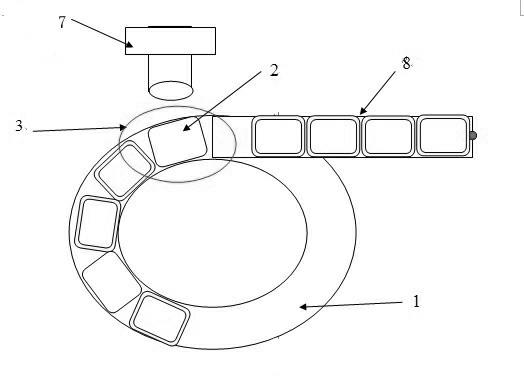
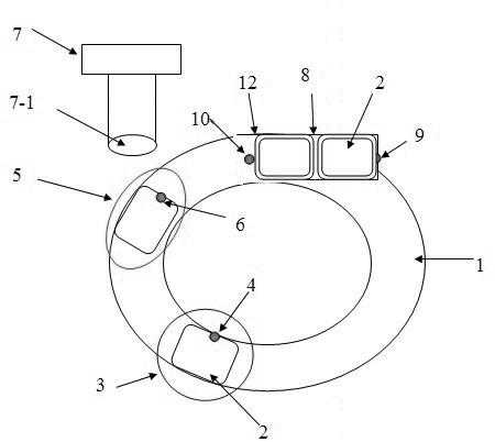
[0013] See figure 2 , the present invention comprises a vibrating plate, a circular track 1 is arranged on the vibrating plate, a cover 2 is placed on the circular track 1, the initial position on the circular track 1 and the cover 2 is placed on it is set as a pre-screening area 3, Set the first sensor 4 in the pre-screening area 3, the first sensor 4 is a high-sensitivity optical fiber digital display sensor (Keyence fiber optic sensor), the first sensor 4 is located inside the circular track 1 and on the edge of the cover 2 , the cover 2 centrifugally vibrates with the circular track 1, a second sensor 6 is set at the middle position 5 of the circular track 1, the second sensor 6 is an external trigger sensor of the optical recognition system, and the second sensor 6 is located on the edge of the cover, The optical recognition system 7 is located above the position 5 in the middle of the circular track, and picks up the front of the track 8. Its optical lens 7-1 faces the...


PUM


Abstract

The invention provides a reverse cover screening system which can improve the efficiency of automatically screening reverse covers and well avoids product appearance and performance defects. The reverse cover screening system comprises a vibration plate, wherein the vibration plate is provided with a circular orbit, the tail end of the circular orbit is provided with a pickup orbit, the pickup orbit is a section of straight vibration orbit, and an optical recognition system is positioned in front of the pickup orbit and above the circular orbit. The reverse cover screening system provided by the invention is characterized in that the initial position of the circular orbit is provided with a pre-screening area, a first inductor is arranged in the pre-screening area, the first inductor is positioned at the edge of a cover close to the inner side of the circular orbit, the middle section of the circular orbit is provided with a second inductor, the second inductor is positioned at the frontmost edge of the cover along the advancing direction of the orbit, and an optical lens of the optical recognition system faces the frontmost edge of the cover on the circular orbit along the advancing direction of the orbit.

Description

technical field [0001] The present invention relates to the SMD (Surface Mount Device) product packaging process, in particular to a screening system with a series of functions such as classification, identification, and screening of the positive and negative sides of special gold-tin alloy covers, specifically a screening system with reverse covers . Background technique [0002] With the rapid development of communication, electronics and other related industries, the packaging requirements of SMD products are getting higher and higher, and any packaging defects cannot be accepted by customers. SMD products include a cover and a shell. The assembly of the cover and the shell is called packaging. Using gold-tin solder reflow soldering technology, the cover and the ceramic shell are welded and fixed by instantaneous high temperature. However, in the actual production process, often appear on the cover reverse defect. Existing cover reverse screening systems see figure 1 ...

Claims


Application Information

Patent Timeline
Patent Type & Authority Applications(China)
IPC IPC(8): G01N21/89
Inventor 章峰
Owner RF360 TECH (WUXI) CO LTD
Why Eureka
Try Eureka