Infrared imaging system

a technology of infrared imaging and infrared light, applied in the field of infrared light imaging systems, can solve the problems of incomplete sensor systems, inability to detect, recognize or identify threats at very long range, and inability to provide the highest levels of performance, so as to improve detection, recognition and identification range, and effective retrofit option for sensor systems

Active Publication Date: 2014-01-02
RAYTHEON CO
View PDF2 Cites 10 Cited by
  • Summary
  • Abstract
  • Description
  • Claims
  • Application Information

AI Technical Summary

Benefits of technology

[0004]Certain embodiments are directed to an infrared imaging sensor that supports upgrades to 2nd Generation Forward Looking Infrared (FLIR) Horizontal Technology Integration (HTI) B-Kit based sensors by fitting with space available within applicable A-Kits and providing significantly improved detection, recognition, and identification range.
[0005]Aspects and embodiments are directed to a FLIR B-kit that includes a set of refractive opto-mechanical modules and backward-compatible electronics modules which may be used to upgrade existing Second Generation FLIR HTI B-kit based sensor systems to provide greatly extended identification range and / or an ultrawide field of view (FOV). Electronics modules can also be used to sustain Second Generation FLIR HTI sensors. Embodiments of the FLIR B-kits are configured to fit within the footprint of existing Second Generation FLIR HTI B-kit modules, thereby providing an effective retrofit option for sensor systems.

Problems solved by technology

Some conventional FLIR kits do not provide the ability to detect, recognize or identify threats at very long range, for example, at ranges that exceed the threat engagement range or maximum munitions range.
In addition, the sensor field of view may be narrower than may be desired to support short acquisition times. Attempts to upgrade FLIR modules for improved performance with advances in technology have included replacing the entire sensor system (which is expensive), and upgrading with small pixel longwave infrared (LWIR) sensors which, although providing better performance than the sensors used in some older systems, still do not provide the highest levels of performance, due to limitations of a single spectral band in a space constrained installation.

Method used


Image

  • Infrared imaging system
  • Infrared imaging system
  • Infrared imaging system

Examples


Embodiment Construction

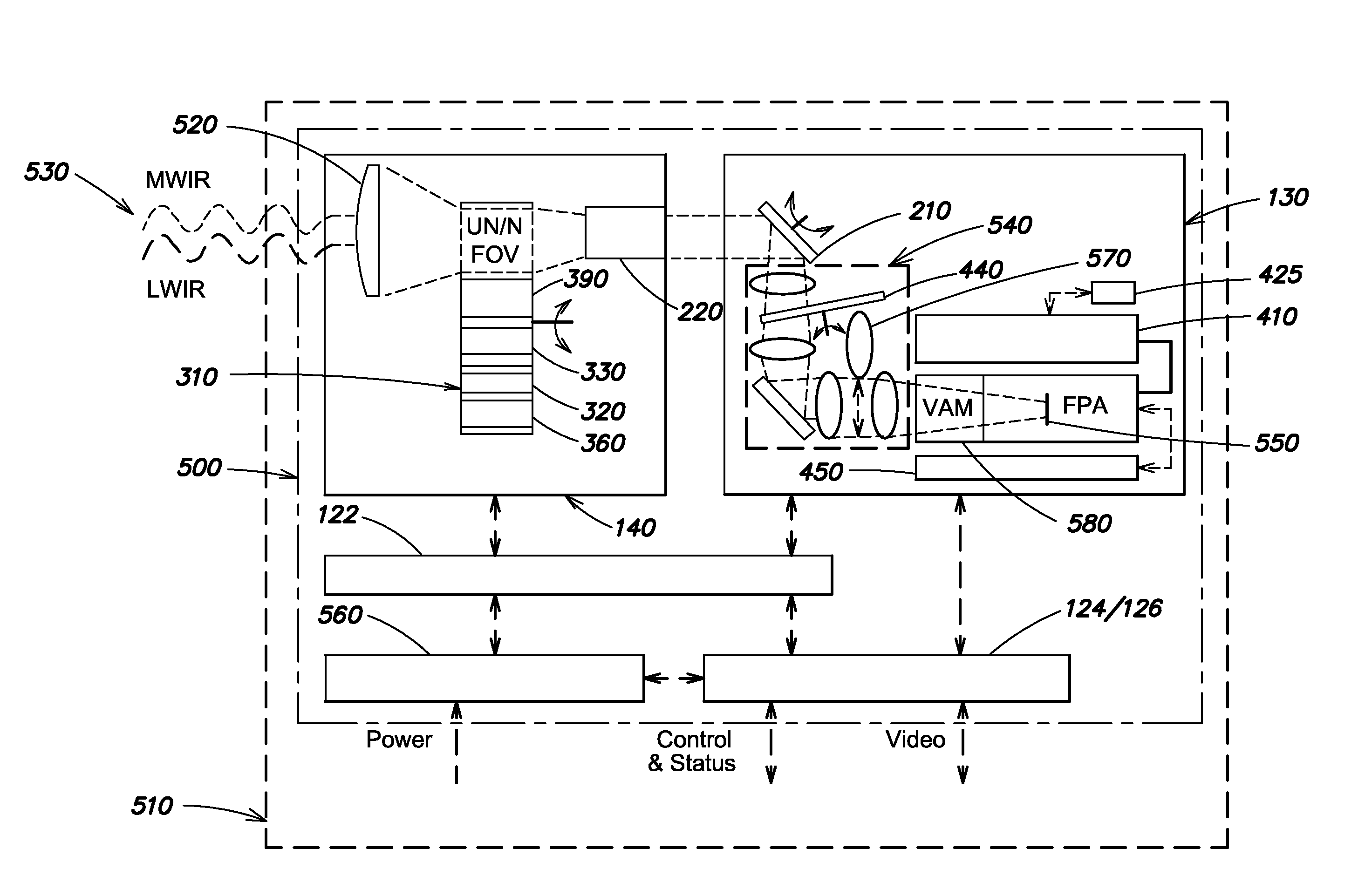
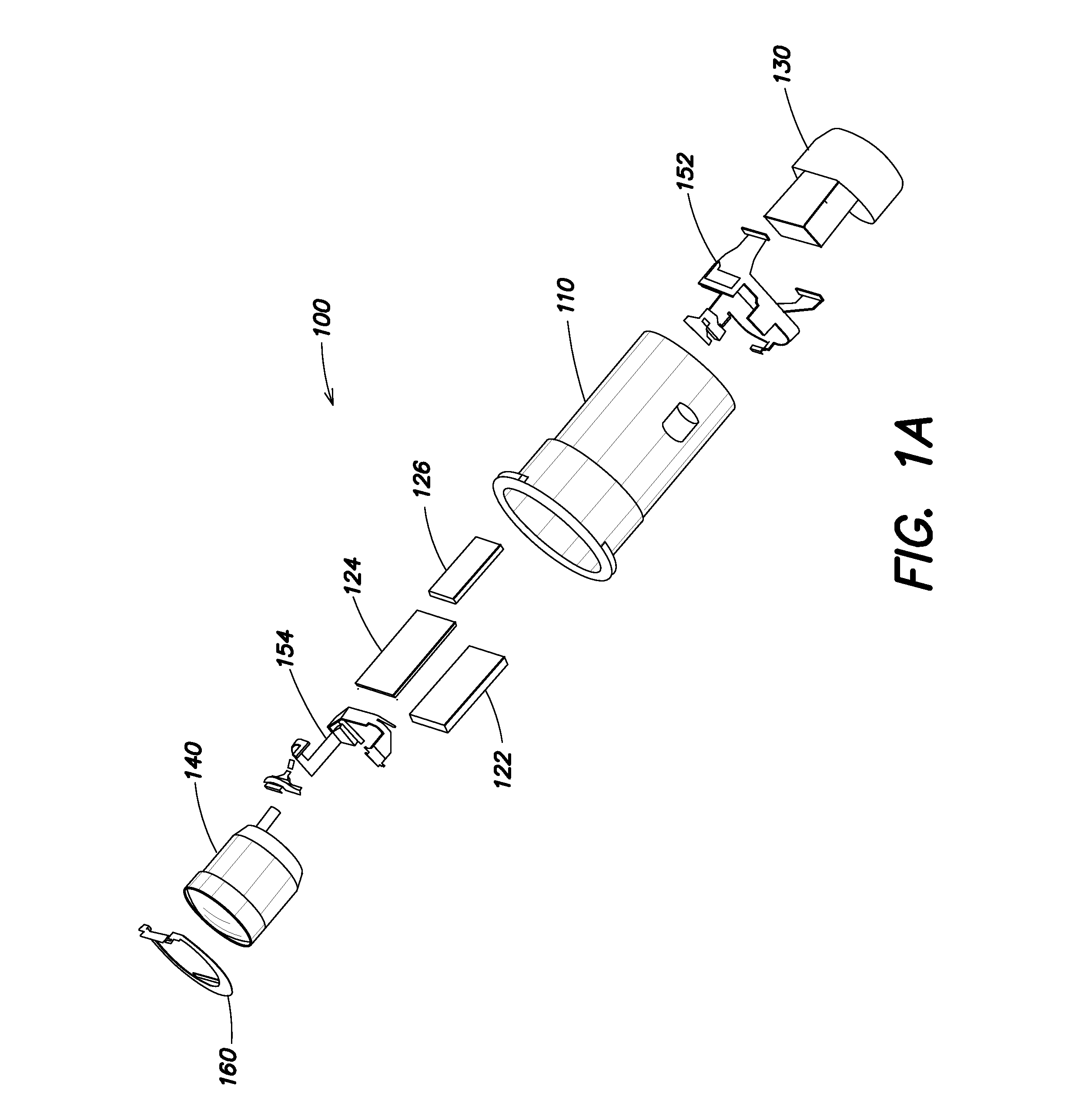
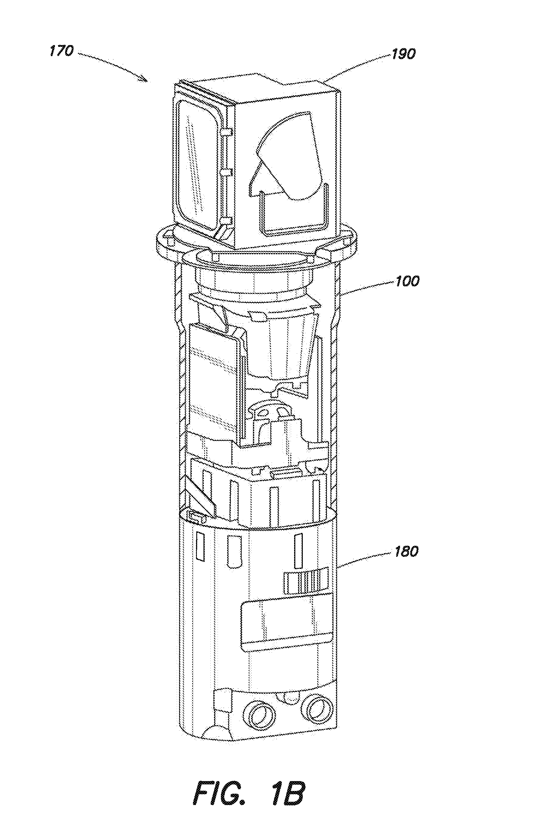
[0027]Aspects and embodiments are directed to a FLIR B-kit, optionally referred to as a Third Generation FLIR B-kit, which can be used to upgrade sensor systems that use existing Second Generation FLIR HTI B-kit modules. In one embodiment, the FLIR B-kit includes a set of infrared (IR) sensor modules, including one or more refractive opto-mechanical modules and electronics modules. The electronics modules may include electronic circuit card assemblies that are backward compatible with legacy Second Generation FLIR B-kits and forward compatible with Third Generation FLIR B-kits. Backward compatibility provides obsolescence mitigation to Second Generation FLIR HTI modules, and forward compatibility allows Third Generation FLIR B-kits to reuse the electronics modules while upgrading Second Generation FLIR B-kits with new features. Embodiments of the FLIR B-kit, in addition to matching field of view of the existing Second Generation FLIR HTI B-Kit, provide a field of view that provides ...


PUM


Abstract

An infrared imaging sensor compatible with 2nd Generation Forward Looking Infrared (FLIR) Horizontal Technology Integration (HTI) B-Kit based sensors. In one example, the infrared imaging sensor includes a set of refractive opto-mechanical modules, including an afocal optical module, a receiver assembly, and backward- and forward-compatible electronics modules. The afocal optical module is configured to provide a plurality of different fields of view for the infrared imaging sensor. In one example, the sensor is configured for MWIR and LWIR imagery.

Description

CROSS REFERENCE TO RELATED APPLICATIONS[0001]This application claims the benefit under 35 U.S.C. §119(e) of co-pending U.S. Provisional application No. 61 / 666,239, filed on Jun. 29, 2012 and titled “INFRARED IMAGING SYSTEM,” which is herein incorporated by reference in its entirety.BACKGROUND[0002]Forward Looking Infrared (FLIR) imaging systems are used in many applications by many organizations, including the U.S. Army. A common module approach has been adopted for the production and fielding of FLIR systems to allow common access to core FLIR components in order to reduce costs and facilitate maintenance, while maintaining flexibility in the sensor configuration and a common look and feel between sensors. The Army uses FLIR kits (that include one or more FLIR modules) in the majority of ground combat vehicle platform sensors. For example, weapon sights that are based on FLIR technology support battlefield surveillance and target acquisition. They allow gunners and field commanders...

Claims


Application Information

Patent Timeline
Patent Type & Authority Applications(United States)
IPC IPC(8): H04N5/33G01S17/04
CPCH04N5/33G02B13/146G02B23/12G01S7/497G01S7/481G01S17/04
Inventor KINGDON, FREDERIC W.FOLEY, MICHAEL G.ERNEST, MICHAEL D.STROTHER, GEORGE T.MARKASON, DAVID J.JUERGENS, RICHARD C.
Owner RAYTHEON CO
Why Eureka
Try Eureka