Single-phase traction transformer for high-speed electrified railway in AT (auto-transformer) power supply way

A technology for electrified railways and traction transformers, applied to transformers, fixed transformers, circuits, etc., can solve the problems of complex structure, unsatisfactory and high cost of transformers

Inactive Publication Date: 2012-05-02
WOLONG ELECTRIC GRP CO LTD +1
View PDF4 Cites 6 Cited by
  • Summary
  • Abstract
  • Description
  • Claims
  • Application Information

AI Technical Summary

Problems solved by technology

[0002] At present, the traction transformers commonly used in my country for AT power supply include Scott wiring traction transformer and VX wiring traction transformer. The Scott transformer is composed of two single-phase traction transformers, T transformer and M transformer. T transformer and M transformer need to be designed separately. , the structure of

Method used


Image

  • Single-phase traction transformer for high-speed electrified railway in AT (auto-transformer) power supply way
  • Single-phase traction transformer for high-speed electrified railway in AT (auto-transformer) power supply way

Examples


Embodiment Construction

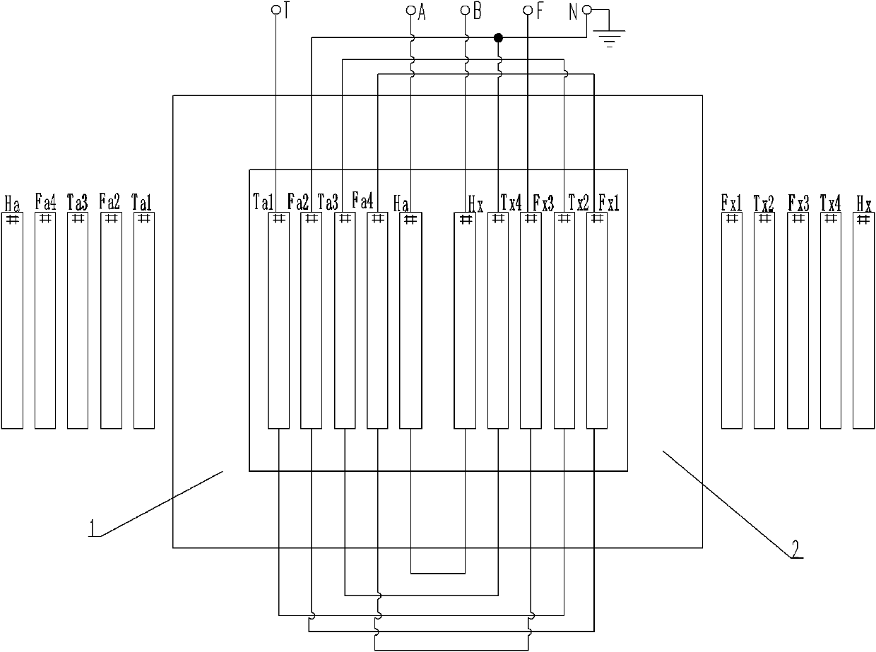
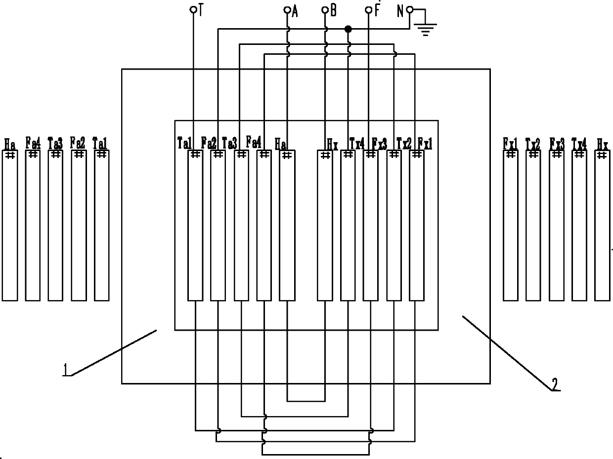
[0016] The technical solution of the present invention will be further described in detail below in conjunction with the accompanying drawings.

[0017] The transformer iron core of the present invention adopts a single-phase two-column structure iron core, including a core column group and a winding concentrically socketed on the iron core column, and the iron core column group includes a first iron core column 1, a second iron core Column 2, the iron core column is connected with five concentric winding layers from inside to outside, which are respectively the first winding layer, the second winding layer, the third winding layer, the fourth winding layer, and the fifth winding layer; wherein the first iron core The first winding layer of column 1 is the first winding Ta1 on the power supply side, the second winding layer is the second winding Fa2 on the feeding side, the third winding layer is the third winding Ta3 on the power supply side, and the fourth winding layer is th...


PUM


Abstract

The invention relates to a single-phase traction transformer for a high-speed electrified railway in an AT (auto-transformer) power supply way. The conventional traction transformer for AT power supply consists of a T-transformation single-phase traction transformer and an M-transformation single-phase traction transformer, and the two transformers need to be separately designed, have complicated structures and high manufacturing difficulty and difficultly meet design requirements. The single-phase traction transformer is characterized in that: an iron core is in a single-phase two-column structure; iron core columns are sleeved with five concentric winding layers from the inner side to the outer side; a first winding, a second winding, a third winding and a fourth winding on a power supply side are connected in series to form a power supply side output end; a third winding, a fourth winding, a first winding and a second winding on a feed side are connected in series to form a feed side output end; and a primary side first winding is connected in series with a primary side second winding to form a phase A input end and a phase B input end. In the single-phase traction transformer, the T-transformation single-phase traction transformer and the M-transformation single-phase traction transformer are uniformly designed into the traction transformer, so that the single-phase traction transformer has a simple structure, meets design requirements and lowers design and production cost.

Description

technical field [0001] The present invention relates to a traction transformer. Background technique [0002] At present, the traction transformers commonly used in my country for AT power supply include Scott wiring traction transformer and VX wiring traction transformer. The Scott transformer is composed of two single-phase traction transformers, T transformer and M transformer. T transformer and M transformer need to be designed separately. , the structure of the whole transformer is complex and difficult to manufacture, the outlet voltage of the secondary side is 55kV, the outlet autotransformer 55 / 27.5kV is required for power transformation, and the cost is high; it cannot meet the AT power supply mode VX wiring traction transformer Z 21 = Z 31 , (3Z 21 +Z 31 -Z 23-1 ) / 4<0.3Ω design requirements. where Z 21 is the impedance seen from the supply side winding after the primary winding is short-circuited, Z 31 is the impedance seen from the feed-side winding after...

Claims


Application Information

Patent Timeline
IPC IPC(8): H01F30/10H01F27/30H01F27/28
Inventor 鲁玮张健马君
Owner WOLONG ELECTRIC GRP CO LTD
Why Eureka
Try Eureka