
Magnetostrictive linear driver with linear output

A magnetostrictive, linear drive technology, applied in the direction of piezoelectric effect/electrostrictive or magnetostrictive motors, generators/motors, electrical components, etc., can solve problems such as difficult precision control, and achieve good linear output , low cost effect

Inactive Publication Date: 2014-09-10
NANCHANG INST OF TECH
View PDF3 Cites 0 Cited by
  • Summary
  • Abstract
  • Description
  • Claims
  • Application Information

AI Technical Summary

Problems solved by technology

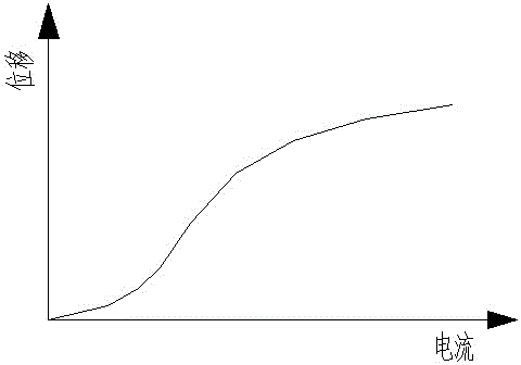
However, due to the nonlinear characteristics of the material itself, the output displacement of the magnetostrictive rod has a nonlinearity similar to that of the material, such as figure 2 As shown, it has caused great difficulties for precise control

Method used


Image

  • Magnetostrictive linear driver with linear output
  • Magnetostrictive linear driver with linear output
  • Magnetostrictive linear driver with linear output

Examples


Embodiment 1

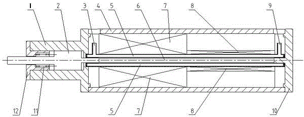
[0014] Example 1 is attached Figure 1-3 Shown: A linear output magnetostrictive linear actuator, including one end of the cylindrical shell 4 fixedly connected to the guide sleeve 1, the other end of the cylindrical shell 4 fixedly connected to the closed end cap 10, a hollow water cooling sleeve 5 The closed two ends are respectively installed in the center of the guide sleeve 1 and the end cover 10, the two ends of the hollow water cooling sleeve 5 are respectively provided with a water inlet pipe 3 and a water outlet pipe 9, and the magnetostrictive rod 6 is mounted on the hollow water cooling sleeve 5 with clearance fit. Center; the coil connected with the current source is installed in the annular space between the inner wall of the cylindrical shell 4 and the hollow water-cooling sleeve 5, and one end of the output shaft 2 that is slidingly fitted with the inner cavity of the guide sleeve 1 penetrates into the hollow water-cooling sleeve 5 center, and close to the end o...

Embodiment 2

[0016] Embodiment 2: In the magnetostrictive linear actuator with linear output described in Embodiment 1, the number of layers wound radially by 1# coil 7 is 60 layers, and the number of layers wound radially by coil 8 of 2# is 12 layer.

Embodiment 3

[0017] Embodiment 3: In the magnetostrictive linear actuator with a linear output described in Embodiment 1, the number of layers wound radially by 1# coil 7 is 70 layers, and the number of layers wound radially by coil 8 of 2# is 18 layer.


PUM


Abstract

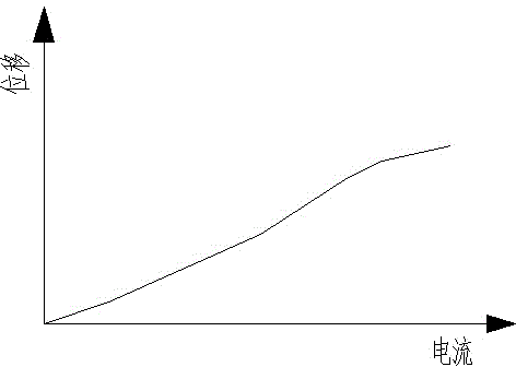
The invention relates to a linear output magnetostrictive linear driver, which is provided with two radial coils of 1# and 2# connected end-to-end with different winding layers. Driven by the source, the axial length of the two coils is the same, and their sum is equal to the length of the magnetostrictive rod; The magnetic induction intensity of the magnetostrictive rod is high, and the magnetic induction intensity of the second half of the magnetostrictive rod located in the 2# coil is lower, so that the deformation of the two magnetostrictive rods is inconsistent, and each part produces uneven expansion and contraction along the axial direction, but Combined, after the deformation output of each part is superimposed, the linearity of the total deformation of the magnetostrictive rod is better than that of the traditional magnetostrictive linear driver with a uniform magnetic field, so that the present invention has good linear output.

Description

technical field [0001] The invention relates to a magnetostrictive driver, in particular to a linear output magnetostrictive linear driver. Background technique [0002] One end of the cylindrical shell of the existing magnetostrictive linear drive is fixedly connected to the guide sleeve, the other end of the cylindrical shell is fixedly connected to the closed end cap, and the closed two ends of the hollow water-cooling sleeve are respectively installed on the guide sleeve and the end cover. In the center of the cover, the two ends of the hollow water-cooling casing are respectively provided with water inlet pipes and water outlet pipes, and the magnetostrictive rod is installed in the center of the hollow water-cooling casing; the coil connected with the current source is installed on the inner wall of the cylindrical shell and the hollow In the annular space between the water-cooling sleeves, one end of the output shaft that slides with the inner cavity of the guide slee...

Claims


Application Information

Patent Timeline
Patent Type & Authority Patents(China)
IPC IPC(8): H02N2/02
Inventor 卢全国唐刚徐斌周敏刘坤陈定方刘德辉祝志芳陶珍舒亮陶孟仑赵亚鹏
Owner NANCHANG INST OF TECH
Learn More