
Lathe center frame

A technology of center frame and lathe, which is applied in the direction of turning equipment, large fixed members, auxiliary devices, etc. It can solve the problems of easy wear and tear of jaws, achieve the effect of reducing cost consumption and improving service life

Inactive Publication Date: 2012-05-09
陶晓明
View PDF0 Cites 10 Cited by
  • Summary
  • Abstract
  • Description
  • Claims
  • Application Information

AI Technical Summary

Problems solved by technology

[0002] At present, the center frame used for domestic lathe processing is produced by the machine tool parts factory. During use, the matching parts of the jaws and the workpiece need to be oiled, and the jaws are easy to wear during use.

Method used


Image

  • Lathe center frame
  • Lathe center frame

Examples


Embodiment Construction

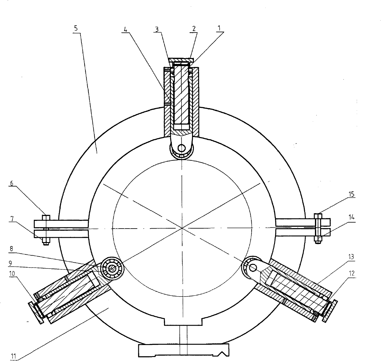
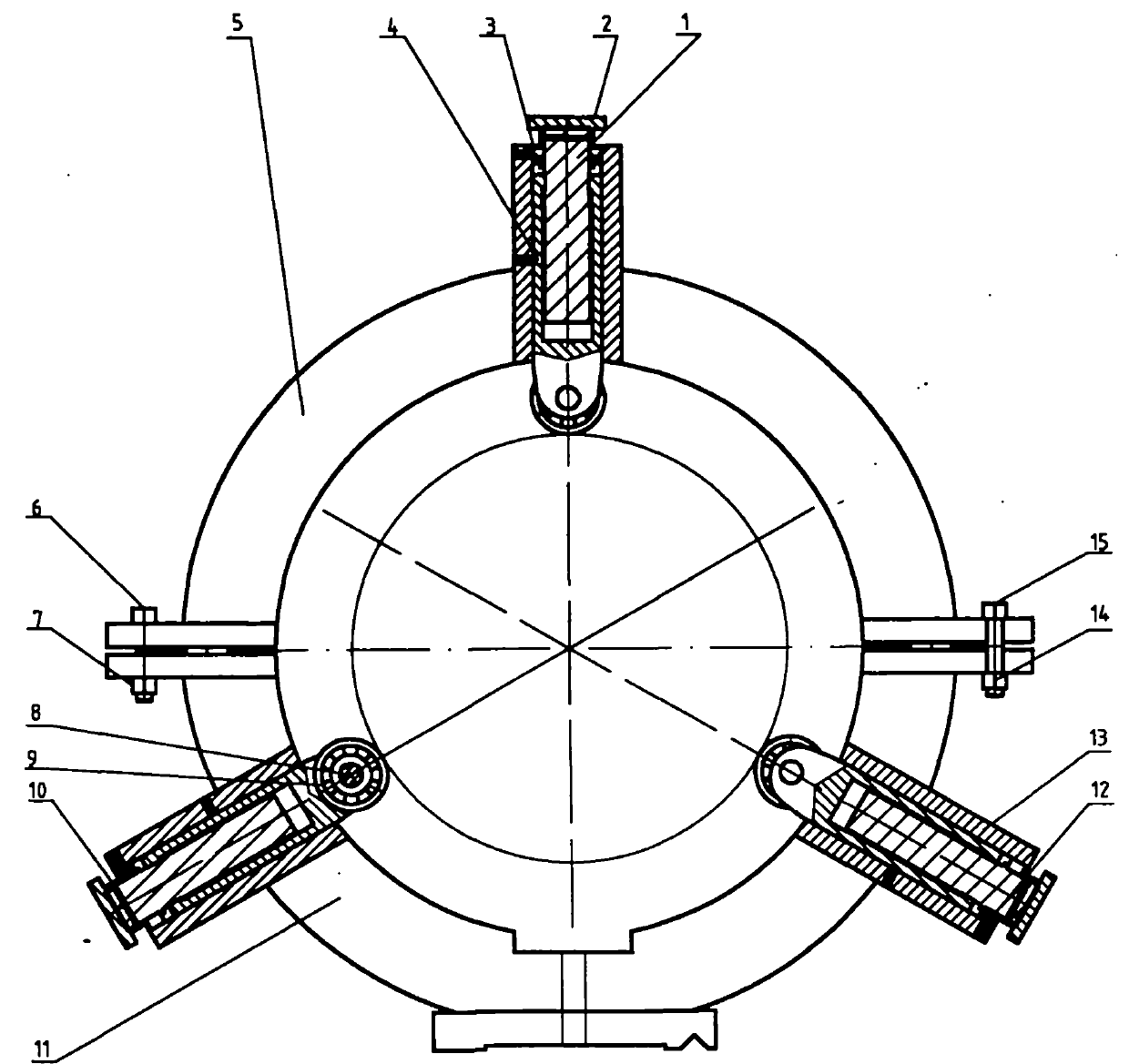
[0012] As shown in the figure, the center screw (1) is screwed into the jaw (4), the upper end of the center screw (1) is covered with the screw fixing sleeve (3), the center screw (1) and the screw adjusting screw sleeve ( 2) Fix it with the fixing pin (10), and put the combination of the central screw rod (1), jaws (4), screw adjusting screw sleeve (2) and screw fixing sleeve (3) into the clamping jaw fixing sleeve ( 13), the screw mandrel fixing sleeve (3) is fixed in the fixing sleeve (13) by the jaw fixing pin (12). The movable frame (5) and the fixed frame (11) are fixed by bolts (6), nuts (7), bolts (15), and nuts (14). The jaws (4) are in contact with the workpiece, and the radial ball bearing rotates around the center of the workpiece under the action of the cutting force.


PUM


Abstract

The invention discloses a lathe center frame. A radial ball bearing is arranged in a slot at the middle of the front end of a clamping jaw which is used generally, and the radial ball bearing rotates around a workpiece under the action of a cutting force, thus abrasion of the clamping jaw is reduced. The invention has the advantages of prolonging the service life of a clamp and reducing the cost consumption through application.

Description

Technical field [0001] The invention relates to a lathe center frame. Background technique [0002] At present, the center frame used for domestic lathe processing is produced by machine tool parts factories. During use, the matching parts of the jaws and the workpiece need to be oiled, and the jaws are easy to wear during use. Contents of the invention [0003] In order to overcome the problem that the center frame of the lathe currently used is easy to wear and tear during use, the invention provides a center frame of the lathe, which has a simple structure, is easy to manufacture, and is convenient to operate. [0004] The technical method adopted in the present invention is to install a radial ball bearing with a groove in the middle of the front end of the commonly used jaw, and the radial ball bearing rotates around the center of the workpiece under the action of cutting force to reduce the wear of the jaw. [0005] The beneficial effect of the present invention is ...

Claims


Application Information

Patent Timeline
Patent Type & Authority Applications(China)
IPC IPC(8): B23Q1/76B23B25/00
Inventor 陶晓明
Owner 陶晓明
Learn More