Rotating shaft structure

A rotating shaft structure and rotating shaft technology, applied in the direction of pivot connection, etc., can solve the problems of poor torque stability of rotating shaft, sensitive interference amount, difficulty in ensuring interference amount and rotation angle, etc., so as to avoid strong impact, ensure continuous and stable change, and meet the requirements of The effect of human requirements

Active Publication Date: 2012-05-09
BYD CO LTD
View PDF8 Cites 3 Cited by
  • Summary
  • Abstract
  • Description
  • Claims
  • Application Information

AI Technical Summary

Problems solved by technology

[0005] The present invention solves the technical problem that the frictional force and output torque of the existing clad rotating shaft are very sensitive to the interference amount, and it is difficult to ensure the relationship between the interference amount and the rotation angle after the assembly of the rotating shaft in actual production, resulting in poor torque stability of the rotating shaft. Provides a wrap-around shaft structure with self-closing function

Method used


Image

  • Rotating shaft structure
  • Rotating shaft structure
  • Rotating shaft structure

Examples


Embodiment Construction

[0041] In order to make the technical problems, technical solutions and beneficial effects solved by the present invention clearer, the present invention will be further described in detail below in conjunction with the accompanying drawings and embodiments. It should be understood that the specific embodiments described here are only used to explain the present invention, not to limit the present invention.

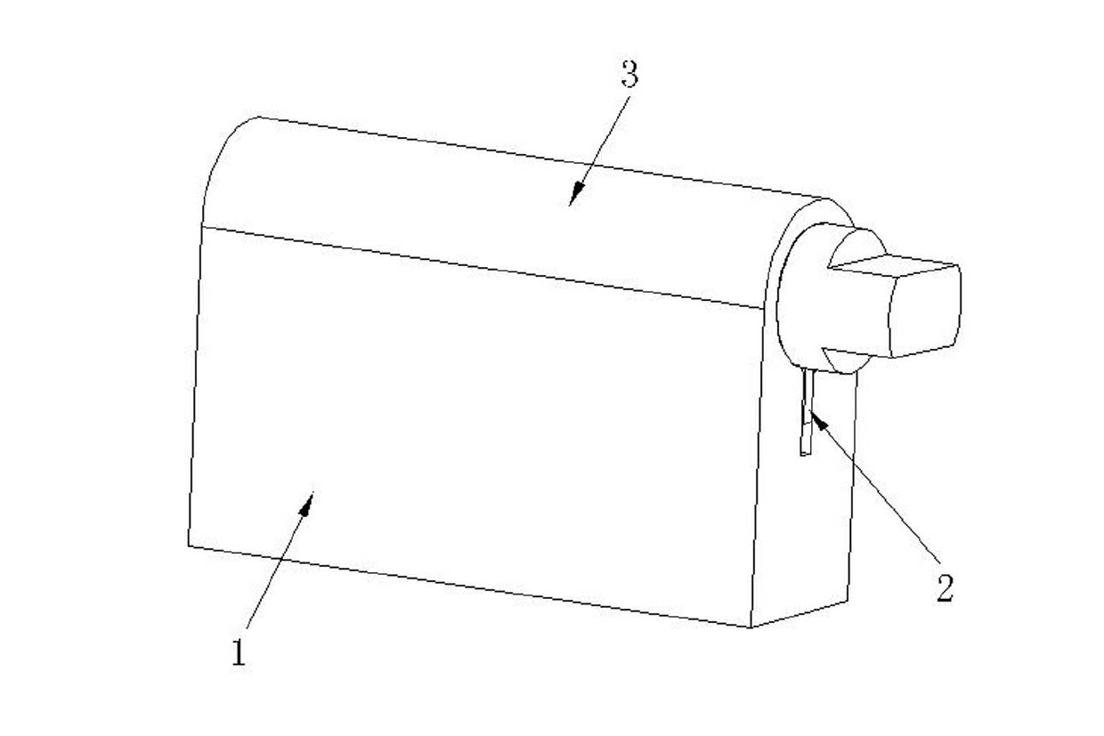
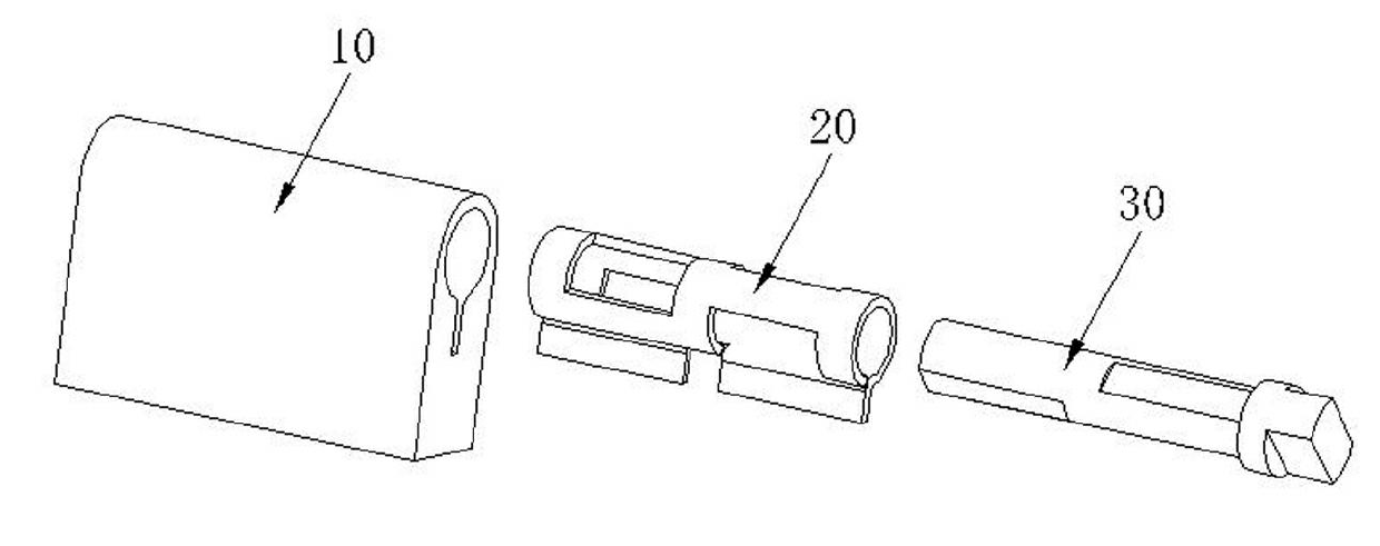
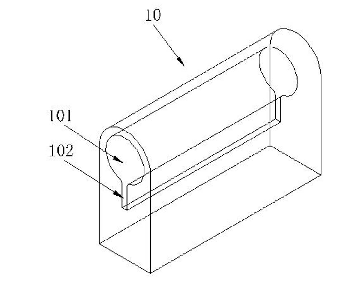
[0042] Aiming at the series of problems of the existing automatic closing function rotating shaft, the inventor found through research that, while the interference amount is basically unchanged, changing the local shape of the spring piece and the rotating shaft will change the size of the frictional contact area with the change of the rotation angle . The frictional contact area is directly proportional to the output torque, so the output torque and rotation required by the automatic closing function can be achieved by reasonably designing the automatic closing angle ra...


PUM


Abstract

The invention provides a rotating shaft structure which comprises a base body, a spring piece and a rotating shaft, wherein the base body is axially provided with a cylindrical hole and an axially extended guide groove connected to the bottom of the cylindrical hole; the spring piece is in close fit with the base body, and comprises a cylindrical tube which is provided with a notch and which is adjacent to the inner wall of the cylindrical hole; the cylindrical tube is provided with at least one hollowed-out zone; a guide locating plate connected with the cylindrical tube is in close fit with the guide groove; at least one flat zone is formed on the surface of the rotating shaft; the one end, provided with the flat zone, of the rotating shaft is arranged in the cylindrical tube of the spring piece, and the other end of the rotating shaft is provided with shaft shoulder gears used for limiting the axial movement of the spring piece; when the rotating shaft rotates relative to the spring piece, under the combined action of the hollowed-out zone and the flat zone, the contact area of the inner surface of the cylindrical tube and the outer surface of the rotating shaft changes along with the rotating angle of the cylindrical tube and the rotating shaft, thereby generating different friction torques. According to the invention, the torque change is realized through the change of the contact area, thus the regularity of the torque changing along with the rotating angle is easy to control and implement.

Description

technical field [0001] The invention belongs to the field of rotating shafts, in particular to a rotating shaft structure with an automatic closing function. Background technique [0002] In daily life, in order to make the foldable objects open and close smoothly, a rotating shaft structure is usually installed between two opposite rotating components. Among the existing hinge structures, the wrapped hinge is widely used on foldable objects due to its relatively low manufacturing cost, so as to provide a certain torque. [0003] At present, the realization of the automatic closing function of the rotating shaft mainly relies on two types of structures. One is the shrapnel structure using cam interference components. The axial displacement is generated by the axial rotation between the cams, and the extrusion degree of the shrapnel changes sharply, resulting in a drastic change in the output torque of the shaft, realizing the automatic closing function of automatic closing ...

Claims


Application Information

Patent Timeline
Patent Type & Authority Applications(China)
IPC IPC(8): F16C11/12
Inventor 何露喜蒋丛华周虎
Owner BYD CO LTD
Why Eureka
Try Eureka