Filtering module of electronic signal connector

A filter module and electronic signal technology, applied in the direction of high-frequency structural connection, etc., can solve problems such as unstable network signal transmission, occupation, and difficulty in automatic manufacturing

Inactive Publication Date: 2012-05-09
AJOHO ENTERPRISE
View PDF2 Cites 4 Cited by
  • Summary
  • Abstract
  • Description
  • Claims
  • Application Information

AI Technical Summary

Problems solved by technology

[0003] The types of general networks can be roughly divided into regional networks, metropolitan networks, wide area networks, wireless networks, and the Internet according to the geographical scope covered by the computer. When performing network signal connection, uploading, and downloading operations, It is easy to be interfered by the signals and electromagnetic waves of surrounding electronic components, or the surge phenomenon generated by the signal, etc., which will affect the instability of network signal transmission, so filter elements must be installed in the network connector for signal filtering processing, but the filtering components used in current network connectors, see Figure 10 , Figure 11 , Figure 12 As shown, the network connector A is provided with multiple docking terminals A1 in the insertion space A0, and the multiple docking terminals A1 are respectively electrically connected to the circuit board A2, and then electrically connected to the filter element B outside the circuit board A2, and The filter element B is outside the polymetallic core B1, and the coil B11 is respectively wound, and the magnetic induction between the polymetallic core B1 and the coil B11 is used to perform filtering processing. However, there are still many deficiencies, such as:
[0004] (1) When the network connector A is equipped with the filter element B, the volume of the network connector A must be expanded to accommodate the filter element B, which will cause the network connector A to be additionally equipped with a housing A3, which not only increases the manufacturing cost but also increases the assembly process. More time-consuming and labor-intensive
[0005] (2) The filter element B is outside the multi-metal iron core B1, and the coil B11 is wound separately, which causes the volume of each metal iron core B1 to expand and takes up a large space, and there is also a gap between the adjacent metal iron core B1 and the coil B11. It is easy to generate interference, and when the coil B11 is wound due to the small size of the metal core B1, the automatic process is difficult, and the coil B11 needs to be wound manually
[0006] (3) Outside the multi-metal core B1 of the filter element B, after the coils B11 are respectively wound, the multi-coils B11 must be electrically connected to the circuit board A2 of the network connector A, and the multi-coils B11 are extended and pulled outwards in different directions. Stretching, causing the multi-coil B11 to be disordered and irregular, and reducing the arrangement spacing between the multi-metal cores B1, it is easy to affect the instability of the filtering function between the metal cores B1
[0007] Therefore, how to solve the current problem that the metal core of the filter element must be wound with a coil, increase the volume of the network connector, and easily affect the lack of filtering between adjacent metal cores must be improved, that is, the inventor and Relevant manufacturers engaged in this industry are eager to study the direction of improvement

Method used


Image

  • Filtering module of electronic signal connector
  • Filtering module of electronic signal connector
  • Filtering module of electronic signal connector

Examples


Embodiment Construction

[0028] In order to achieve the above-mentioned purpose and effect, the technical means adopted by the present invention and its implementation mode are hereby described in detail with respect to the preferred embodiments of the present invention. Its features and functions are as follows, so that it can be fully understood.

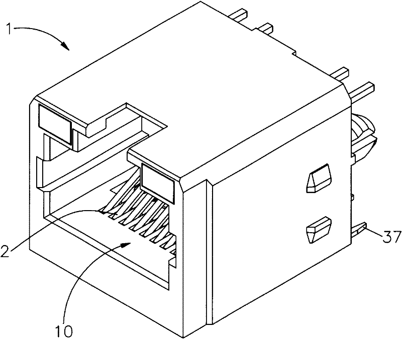
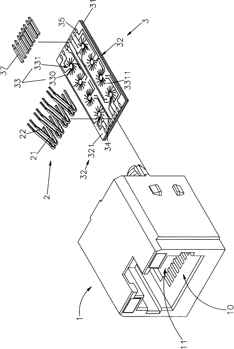
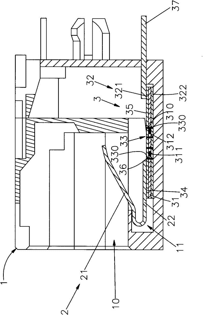
[0029] see figure 1 , figure 2 , image 3 , Figure 4 Shown are the three-dimensional appearance diagram, three-dimensional exploded view, side view section view, and three-dimensional appearance diagram of the filter module of the present invention. It can be clearly seen from the figure that the filter module of the electronic signal connector of the present invention includes an insulating seat body 1. Multi-terminal 2. Filter module 3, in which:

[0030] A hollow docking space 10 is provided inside the insulating base body 1 , and an accommodating space 11 is provided adjacent to the docking space 10 .

[0031] The multi-terminal 2 has a butt si...


PUM


Abstract

The invention provides a filtering module of an electronic signal connector. An insulation seat body of the electronic signal connector is provided with a plurality of terminals in a penetrating manner, and the butt joint sides of the terminals are extended in a butt joint space of the insulation seat body; various welding sides are connected with the filtering module in an accumulating space in an electrical manner; the filtering module is provided with a plurality of transmission terminals in an electrical connection manner which are respectively extended out of the insulation seat body; the filtering module is provided with a metal inner core in the base material; the two lateral surfaces are formed into copper coil layers of a sensing area with preset circuit layout, and the external surfaces of the two copper coil layers are formed into a preset circuit layout of radial shaped multiple metal wires; and a magnetic induction effect of continuously coiled metal magnetic induction loop is formed by mutually connecting and conducting internal metal conductors of various vents and through holes and the radial shaped multiple metal wires, so that the electronic signal connector can perform signal filtering and rectifying. The filtering module provided by the invention can be used for reaching the purpose that the existing volume of the electronic signal connector is not enlarged through the small-volume and low-cost plate-shaped filtering module.

Description

technical field [0001] The invention provides a filter module of an electronic signal connector, especially a filter module that can be used in accordance with the specifications of the electronic signal connector. The multi-terminals of the electronic signal connector are electrically connected to the filter module without enlarging the volume of the electronic signal connector. The size can have effects such as filtering and rectification, and achieve the function of maintaining the existing type of electronic signal connector without changing the design. Background technique [0002] Nowadays, computer technology is developing rapidly, and desktop computers or notebook computers have been widely used in every corner of the society, and the development trend of computers is also moving towards the direction of powerful computing functions, fast speed and small size. In addition, because network communication technology is also It is rapidly developing and bringing people's...

Claims


Application Information

Patent Timeline
Patent Type & Authority Applications(China)
IPC IPC(8): H01R13/719
Inventor 莫家平
Owner AJOHO ENTERPRISE
Why Eureka
Try Eureka