Armature for rotary electric apparatus and manufacturing method for the same
A technology of rotating electric machines and manufacturing methods, which is applied in the direction of manufacturing motor generators, manufacturing stator/rotor bodies, electric components, etc., and can solve problems such as prolonging processing time and prolonging the pressing process
- Summary
- Abstract
- Description
- Claims
- Application Information
AI Technical Summary
Problems solved by technology
Method used
Image

Examples
no. 1 example
[0031] Below, will refer to Figures 1 to 7 An armature of a rotating electrical machine (rotating electrical machine) according to the first embodiment will be described. In this embodiment, the rotating electric machine includes a rotor core (rotor core).
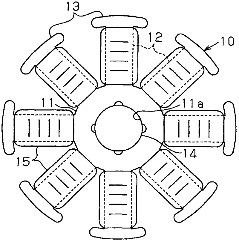
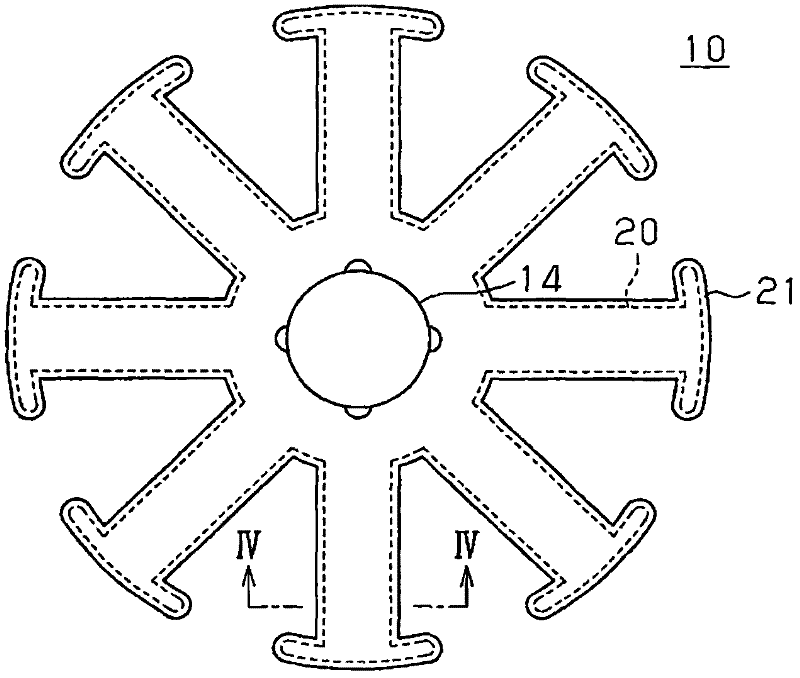
[0032] figure 1 A rotor core related to the present first embodiment is shown. Such as figure 1As shown, the rotor core 10 includes a rotor center portion 11 , eight teeth 12 and ends 13 . The rotor center portion 11 is substantially circular in plan view. Eight teeth 12 protrude radially from the rotor central portion 11 . Tips 13 are respectively located at the ends of teeth 12 . Each end 13 is generally elliptical in plan view. The rotor center portion 11 has an axial insertion hole 11a at the center. The rotary shaft 14 is press-fitted into this axial insertion hole 11a. A winding 15 is wound onto each tooth 12 in a winding direction perpendicular to the direction in which each tooth 12 extends.
[0033] ...
no. 2 example
[0048] Subsequently, will refer to Figures 8 to 10B A rotor core according to a second embodiment is described. Such as Figure 8 As shown, according to the present embodiment, the insulating film 42 is formed on the surface of the laminated core 41 of the rotor core 40 . Such as Figure 8 , 9A , 9B, the laminated iron core 41 includes a first core piece 43a as a single piece, a plurality of second core pieces 43b, and a third core piece 43c as a single piece. The first core sheet 43a, the second core sheet 43b, and the third core sheet 43c are laminated.
[0049] Such as Figure 8 , 9A , 9B, each tooth portion 44a of the first core piece 43a has a width in a direction perpendicular to the extending direction in which the tooth portion 44a extends. That is, each tooth portion 44a has a Figure 9A , 9B The horizontal width of the . The width of each tooth portion 44a of the first core piece 43a is smaller than the width of each tooth portion 44b of the second core pi...
no. 3 example
[0061] Subsequently, will refer to Figure 11 , 12 A rotor core according to a third embodiment is described. Such as Figure 11 As shown, an insulating film 52 is formed on the surface of the laminated core 51 of the rotor core 50 according to the present embodiment. The laminated core 51 includes a first core sheet 53a, a second core sheet 53b, and a third core sheet (not shown) which are laminated. In this embodiment, the structure of the laminated core is basically the same as that of the second embodiment except for the shape of the burr 56a of the first core piece 53a.
[0062] Specifically, in the Figure 11 In the illustrated embodiment, the burr 56a of the tooth portion 54a of the first core sheet 53a is along the direction perpendicular to the direction of lamination of the core sheets 53a, 53b. Figure 11 in the horizontal direction. In this structure of the first core piece 53a, the burr 56a extends in the horizontal direction, and therefore, the burr 56a pro...
PUM
| Property | Measurement | Unit |
|---|---|---|
| thickness | aaaaa | aaaaa |
| thickness | aaaaa | aaaaa |
Abstract
Description
Claims
Application Information
 - R&D
- Intellectual Property
- Life Sciences
- Materials
- Tech Scout
- Unparalleled Data Quality
- Higher Quality Content
- 60% Fewer Hallucinations
Browse by: Latest US Patents, China's latest patents, Technical Efficacy Thesaurus, Application Domain, Technology Topic, Popular Technical Reports.
© 2025 PatSnap. All rights reserved.Legal|Privacy policy|Modern Slavery Act Transparency Statement|Sitemap|About US| Contact US: help@patsnap.com