
Lower vehicle-body structure

A car body and structure technology, applied to the upper structure, upper structure sub-assembly, body, etc., can solve problems such as low ground clearance, achieve the effects of suppressing vibration, ensuring rigidity, and suppressing miniaturization

Inactive Publication Date: 2020-02-21
MAZDA MOTOR CORP
View PDF4 Cites 1 Cited by
  • Summary
  • Abstract
  • Description
  • Claims
  • Application Information

AI Technical Summary

Problems solved by technology

[0008] In addition, although it is also conceivable to form the floor under the floor other than the passage part flatly without providing an under cover, if a member connecting both ends of the floor passage is provided, such a connecting member will be difficult to install from the viewpoint of installability. The structure connected under the floor on both sides of the aisle, so it is located below the floor surface, and there is still a problem with the minimum ground clearance

Method used


Image

  • Lower vehicle-body structure
  • Lower vehicle-body structure
  • Lower vehicle-body structure

Examples


Embodiment Construction

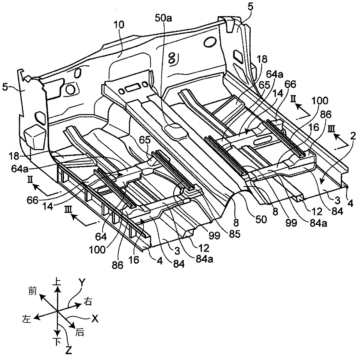
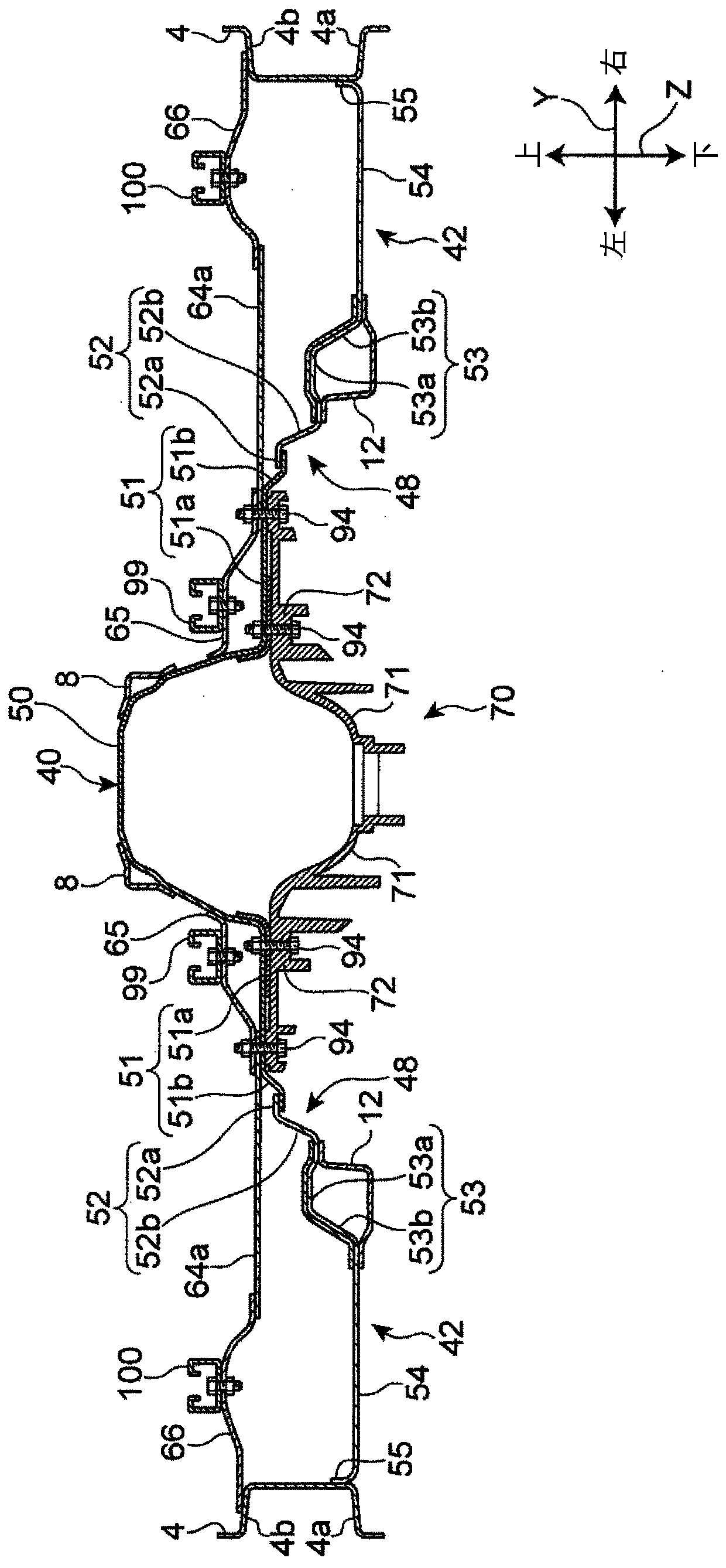
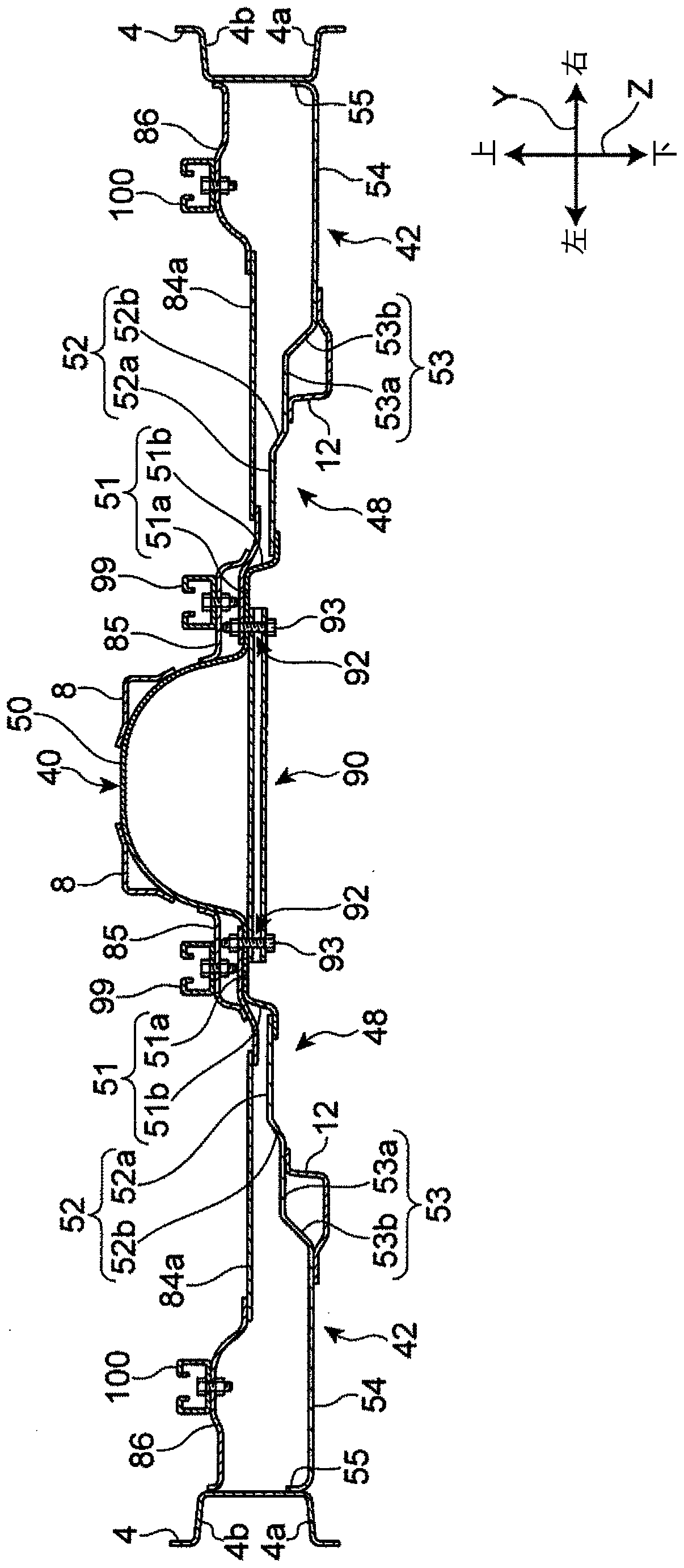
[0038] A lower vehicle body structure according to an embodiment of the present invention will be described below with reference to the drawings. In addition, in the following description, terms indicating directions such as "front", "rear", "right", "left", "upper" and "lower" mean that the Each direction of the vehicle body when the traveling direction when the vehicle travels forward is set to "front". In addition, in the drawings, a symbol "X" is assigned to a vehicle width direction, a symbol "Y" is assigned to a vehicle front-rear direction, and a symbol "Z" is assigned to a vehicle vertical direction.

[0039] [overall composition]

[0040] Such as figure 1 stereogram and figure 2 As shown in the bottom plan view of , the automobile 1 provided with the lower vehicle body structure of this embodiment includes a vehicle body floor 2 constituting the floor of the interior space of the vehicle compartment, and the vehicle body floor 2 along both sides of the vehicle wid...


PUM


Abstract

There is provided a lower vehicle-body structure that allows miniaturization of an undercover and prevents an increase in minimum ground clearance. In the lower vehicle-body structure, a vehicle bodyfloor 2 includes step-up portions 48 connected to a floor tunnel 50 on opposite sides of the floor tunnel 50 in a vehicle width direction at least in regions where first and second cross members 14, 16 are disposed on the vehicle body floor 2. The lower vehicle-body structure includes a mount member 70 that faces the floor tunnel 50 and connects the step-up portions 48 on the opposite sides of thefloor tunnel 50, and includes first and second under covers 102, 104 that cover a lower side of the mount member 70 so as to be continuous with a bottom surface of the vehicle body floor 2 on outer sides of the step-up portions 48 in the vehicle width direction.

Description

technical field [0001] The present invention relates to the underbody structure of a vehicle, and more particularly to an underbody structure with a center tunnel. Background technique [0002] In vehicles such as FR (Front Rear Drive) and 4WD (Four Wheel Drive) vehicles, a propeller shaft extending in the vehicle front-rear direction is provided on a power transmission path from a drive source to drive wheels. The propeller shaft is usually arranged in a floor tunnel provided at the center of the vehicle body floor in the vehicle width direction. In addition, for example, in a vehicle equipped with a so-called longitudinally mounted powertrain, at least a part of the transmission may be disposed in the floor tunnel. [0003] In order to improve the aerodynamic performance of the vehicle, an under cover is provided under the floor to rectify the airflow passing under the floor when the vehicle is running. [0004] For example, Patent Document 1 discloses an undercover for ...

Claims


Application Information

Patent Timeline
Patent Type & Authority Applications(China)
IPC IPC(8): B62D25/20
CPCB62D25/20B62D25/2036B62D25/2045B62D35/02Y02T10/88B60R13/08B62D25/2018
Inventor 戎本圭佑松冈秀典枣裕贵伊川雄希笠木直彦森川阳介
Owner MAZDA MOTOR CORP
Learn More