Multi-blade fan

a multi-blade fan and fan body technology, applied in the direction of non-positive displacement fluid engines, radial flow pumps, pump components, etc., can solve the problems of unfavorable inter-blade pitch angle arrangement, unfavorable inter-blade pitch arrangement, etc., to enhance a noise-reduction property, reduce wind noise, suppress the prominence of specific discrete-frequency nois

Active Publication Date: 2018-11-27
DAIKIN IND LTD
View PDF10 Cites 1 Cited by
  • Summary
  • Abstract
  • Description
  • Claims
  • Application Information

AI Technical Summary

Benefits of technology

[0021]In the multi-blade fan according to the first aspect of the present invention, it is possible not only to reduce wind noise and low-frequency broadband noise, but also to suppress the prominence of specific discrete-frequency noise and to enhance a noise-reduction property.
[0022]In the multi-blade fan according to the second aspect of the present invention, the unpleasantness of noise generated along with the rotation of the multi-blade fan is mitigated.
[0023]In the multi-blade fan according to the third aspect of the present invention, the effect for mitigating the unpleasantness of noise generated along with the rotation of the multi-blade fan is enhanced.
[0024]In the multi-blade fan according to the fourth aspect of the present invention, the effect for mitigating the unpleasantness of noise generated along with the rotation of the multi-blade fan is enhanced.
[0025]In the multi-blade fan according to the fifth aspect of the present invention, a multi-blade fan having a high NZ-noise-dispersing effect is obtained.
[0026]In the multi-blade fan according to the sixth aspect of the present invention, it is possible to minimize problems due to disruption to rotational balance.

Problems solved by technology

However, in conventional methods for determining such inter-blade pitch angle arrangements randomly, the amount by which the NZ noise is reduced changes for each determination of the arrangement, resulting in an unpredictable, ad-hoc method of solution.
This is not an efficient method for determining the inter-blade pitch angle arrangement for blowers in which the cross-flow fans have different specifications, such as with respect to number of blades.

Method used


Image

  • Multi-blade fan
  • Multi-blade fan
  • Multi-blade fan

Examples


Embodiment Construction

[0037](1) Cross-Flow Fan Inside Indoor Unit

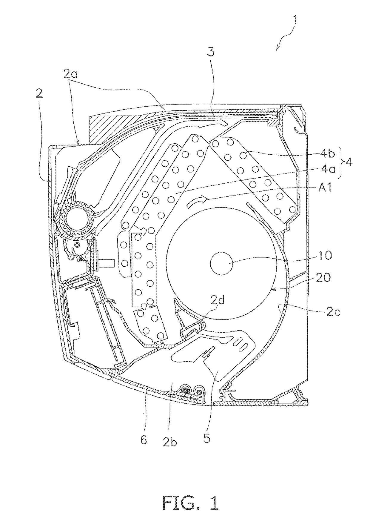
[0038]A cross-flow fan according to a first embodiment of the present invention is described below through the example of a cross-flow fan installed in an indoor unit of an air-conditioning apparatus. FIG. 1 is a schematic view of a cross-section of an indoor unit 1 of an air-conditioning apparatus. The indoor unit 1 comprises a main casing 2, an air filter 3, an indoor heat exchanger 4, a cross-flow fan 10, a vertical flap 5, and a horizontal flap 6.

[0039]As shown in FIG. 1, the air filter 3 is disposed downstream from an intake port 2a in a ceiling surface of the main casing 2 so as to face the intake port 2a. The indoor heat exchanger 4 is disposed further downstream from the air filter 3. The indoor heat exchanger 4 is configured by coupling a front-surface-side heat exchanger 4a and a rear-surface-side heat exchanger 4b so as to form an inverse V-shape as viewed from a side surface. The front-surface-side heat exchanger 4a and the rear...


PUM


Abstract

A multi-blade fan includes a support body rotatable about a rotary shaft, and a plurality of blades secured to the support body such that an inter-blade pitch angle relative to the rotary shaft assumes a prescribed arrangement. The blades extend along an axial direction of the rotary shaft. The plurality of blades are disposed such that, with respect to amplitude values of periodic functions at individual orders when the prescribed arrangement is expanded in a periodic Fourier series, a maximum amplitude value is less than 200% of a second-largest amplitude value.

Description

CROSS-REFERENCE TO RELATED APPLICATIONS[0001]This U.S. National stage application claims priority under 35 U.S.C. § 119(a) to Japanese Patent Application No. 2013-272150, filed in Japan on Dec. 27, 2013, the entire contents of which are hereby incorporated herein by reference.TECHNICAL FIELD[0002]The present invention relates to a cross-flow fan or other type of multi-blade fan.BACKGROUND ART[0003]There are conventionally known blowers in which a cross-flow fan or other type of multi-blade fan is used, wherein wind noise is produced by multiple blades. To counteract a wind noise component having a fundamental frequency related to the number of rotations N and the number of blades Z (referred to below as “NZ noise”) from within the wind noise, values of the angle of the pitch between the blades of the cross-flow fan are arranged at random (random pitch angle arrangement), whereby the inter-blade pitch angle arrangement is varied to reduce noise. Such variation of the inter-blade pitc...

Claims


Application Information

Patent Timeline
Patent Type & Authority Patents(United States)
IPC IPC(8): F04D29/66F04D17/04F04D29/28
CPCF04D29/666F04D29/283F04D17/04
Inventor UDA, MASAFUMI
Owner DAIKIN IND LTD
Why Eureka
Try Eureka