Dual homing protection method and equipment

A dual-homing protection and equipment technology, applied in the field of communication, can solve problems such as link failure and inconsistency of round-trip paths, and achieve the effect of solving inconsistency of back-and-forth paths and link failure

Inactive Publication Date: 2012-05-09
NEW H3C TECH CO LTD
View PDF4 Cites 17 Cited by
  • Summary
  • Abstract
  • Description
  • Claims
  • Application Information

AI Technical Summary

Problems solved by technology

[0005] In view of this, the present invention provides a dual-homing protection method and equipment, which ca

Method used


Image

  • Dual homing protection method and equipment
  • Dual homing protection method and equipment
  • Dual homing protection method and equipment

Examples


Embodiment Construction

[0030] In order to make the object, technical solution and advantages of the present invention clearer, the solutions of the present invention will be further described in detail below with reference to the accompanying drawings and examples.

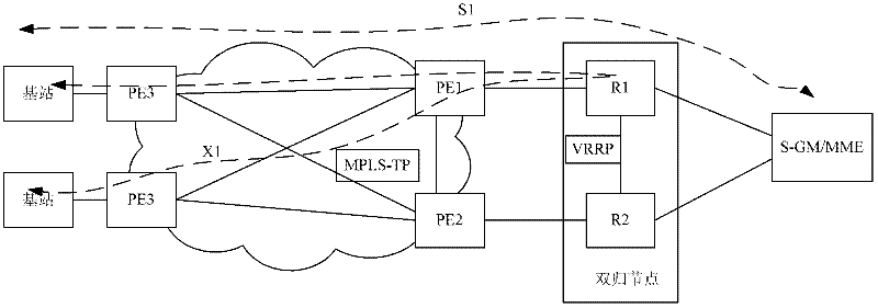
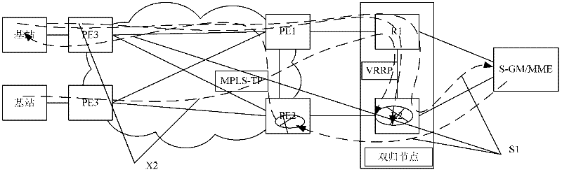
[0031] The present invention proposes a dual-homing protection method, which is applied to a dual-homing network that implements layer-3 equipment. The dual-homing network includes a dual-homing node and a layer-2 MPLS-TP network. The dual-homing node includes two devices, A master device is determined by the priority of the device.

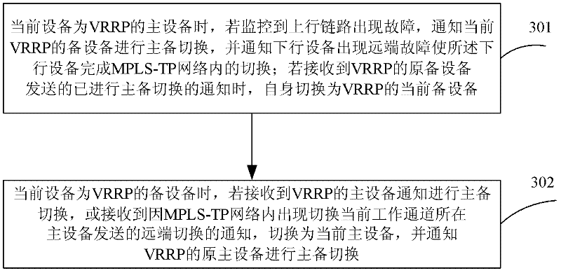
[0032] see image 3 , image 3 It is a schematic flowchart of implementing dual-homing protection in an embodiment of the present invention. The specific steps are:

[0033] Step 301, when the current device is the master device of VRRP, if the monitoring detects that the uplink fails, notify the current VRRP backup device to perform active-standby switchover, and notify the downlink device that a remot...


PUM


Abstract

The invention discloses a dual homing protection method. The method comprises the following steps of: when main equipment of the VRRP monitors an uplink failure, carrying out main/standby switching of a VRRP (Virtual Router Redundancy Protocol) and notifying downlink equipment to carry out switching in an MPLS-TP (Multiple protocol Label Switching-Transport Profile) network; when a link switching appears in the MPLS-TP network, informing the previous main equipment of VRRP by the switched main equipment to carry out the corresponding main/standby switching. Based on the same invention concept, the invention further provides equipment to solve the problems that forward and backward paths are not identical and a link is impassable when an access link breaks down.

Description

technical field [0001] The invention relates to the technical field of communications, in particular to a dual-homing protection method and equipment. Background technique [0002] With the development of mobile technology from 3G to LTE, the mobile backhaul network needs to support the X2 traffic between the LTE base stations while supporting the S1 traffic between the base station and the core network equipment. [0003] In order to prevent the failure of one device from affecting the communication of a large number of base stations, generally two L3 forwarding devices are introduced to form a dual-homing node. see figure 1 , figure 1 It is a schematic diagram of a dual-homing network of three-layer equipment in the prior art. Such as figure 1 As shown, the S1 traffic between the base station and the core network equipment (S-GW or MME) is connected to the network and then reaches R1 through the Layer 2 MPLS-TP network, where R1 is the master device of VRRP, and then c...

Claims


Application Information

Patent Timeline
IPC IPC(8): H04W24/04H04W36/00
CPCH04W24/04H04W36/00H04L41/0668
Inventor 常向青郜忠华姚民刘建锋
Owner NEW H3C TECH CO LTD
Why Eureka
Try Eureka