Liquid discharge head and recording device using same

A liquid ejection head and liquid technology, applied in the direction of inking device, printing, etc., can solve the problem of poor recording accuracy, achieve the effect of weakening pressure vibration and reducing inertia

Active Publication Date: 2012-05-09
KYOCERA CORP
View PDF6 Cites 7 Cited by
  • Summary
  • Abstract
  • Description
  • Claims
  • Application Information

AI Technical Summary

Problems solved by technology

[0010] However, in the liquid ejection head described in Patent Document 1, the liquid droplets ejected by one ejection operation may not be one drop (hereinafter referred to as droplet), but may land as a plurality of liquid droplets. On the recording medium, recording accuracy deteriorates

Method used


Image

  • Liquid discharge head and recording device using same
  • Liquid discharge head and recording device using same
  • Liquid discharge head and recording device using same

Examples


Embodiment Construction

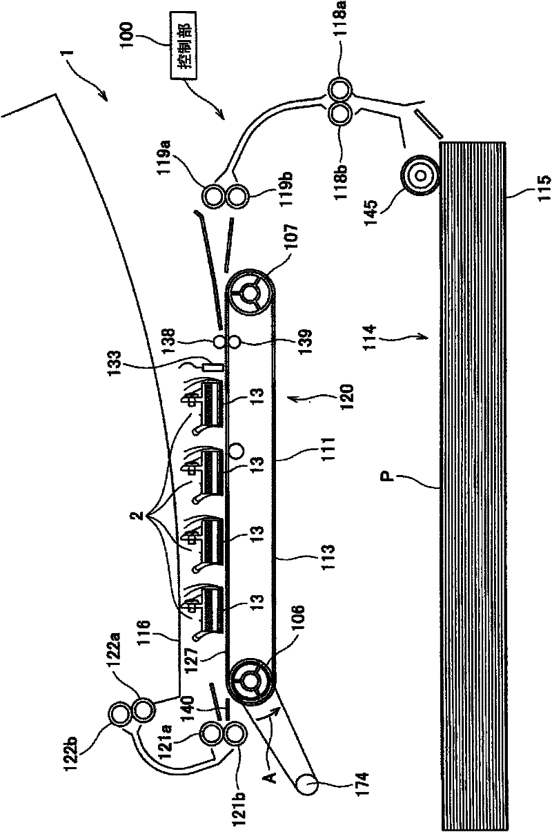
[0024] figure 1 It is a schematic configuration diagram showing a color inkjet printer as an example of a recording device. This color inkjet printer 1 (hereinafter referred to as printer 1 ) has four liquid ejection heads 2 . The above-mentioned liquid ejection heads 2 are arranged along the transport direction of recording paper P as a recording medium, and are fixed to the printer 1 . The liquid ejection head 2 is figure 1 It has an elongated shape towards the depth direction.

[0025] In the printer 1 , a paper feed unit 114 , a conveyance unit 120 , and a paper holder 116 are provided in this order along the conveyance path of the recording paper P. As shown in FIG. In addition, the printer 1 is provided with a control unit 100 for controlling the operation of each part of the printer 1 such as the liquid ejection head 2 and the paper feed unit 114 .

[0026] The paper feed unit 114 has a paper storage cassette 115 capable of storing a plurality of sheets of recording...


PUM


Abstract

Provided are a liquid discharge head by which discharged liquid droplets can be easily gathered into one droplet, and a recording device using the head. A liquid discharge head (2) comprises a liquid pressurizing chamber (10), a displacement element (50) which applies pressure to the liquid pressurizing chamber (10), a liquid discharge hole (8), and a communication path (7) which connects the liquid pressurizing chamber (10) and the liquid discharge hole (8), wherein the communication path (7) comprises a narrow portion (7-3) which has a small cross-sectional area, a first communication path (7-1) defined by a portion between a connection end to the liquid pressurizing chamber (10) and a connection end to the narrow portion (7-3), and a second communication path (7-2) defined by a portion between a connection end to the liquid discharge hole (8); and a connection end to the narrow portion (7-3), and wherein a ratio between a length of the communication path (7) and a length of a second communication path (7-2), a ratio between a synthetic inertance of the liquid pressurizing chamber (10) and the first communication path (7-1) and a synthetic inertance of the liquid discharge hole (8) and the first communication path (7-1), and a ratio between a synthetic compliance of the liquid pressurizing chamber (10) and the first communication path (7-1) and a synthetic compliance of the liquid discharge hole (8) and the first communication path (7-1), are in predetermined ranges.

Description

technical field [0001] The present invention relates to a liquid ejection head such as an inkjet recording head, and a recording device using the liquid ejection head. Background technique [0002] In recent years, printing devices using the inkjet recording method, such as inkjet printers and inkjet plotters, have been widely used not only in printers for general consumers, but also in the formation of electronic circuits and the manufacture of color filters for liquid crystal displays, for example. , Manufacturing of organic EL displays and other so-called industrial uses. [0003] A liquid ejection head for ejecting liquid is mounted on such an inkjet printing device as a printing head. This type of printing head is known in the following two ways: a heater as a pressurizing mechanism is provided in the ink flow path filled with ink, the ink is heated by the heater to make the ink boil, and the air bubbles generated in the ink flow path are used. Pressurize the ink and ...

Claims


Application Information

Patent Timeline
Patent Type & Authority Applications(China)
IPC IPC(8): B41J2/045B41J2/055
CPCB41J2002/14306B41J2202/11B41J2002/14459B41J2002/14225B41J2002/14217B41J2202/20B41J2002/14475B41J2/14209
Inventor 池内涉松元步
Owner KYOCERA CORP
Why Eureka
Try Eureka