Split stator and manufacturing method therefor
A manufacturing method and stator technology, applied in the manufacture of motor generators, stator/rotor body, magnetic circuit shape/style/structure, etc., can solve split stator core and coil short circuit, insulator cracks, insulator insulation reduction, etc. problem, achieve the effect of improving insulation reliability, preventing deformation, and eliminating sliding
- Summary
- Abstract
- Description
- Claims
- Application Information
AI Technical Summary
Problems solved by technology
Method used
Image

Examples
no. 1 approach
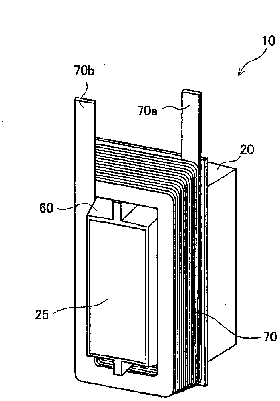
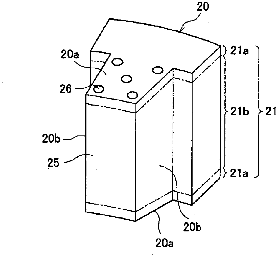
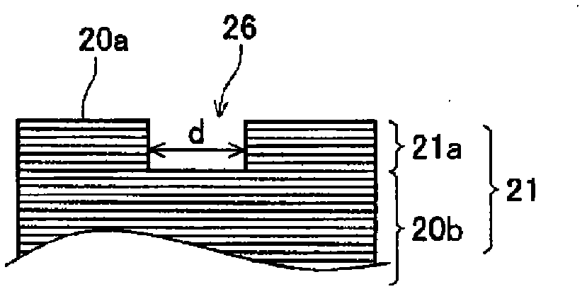
[0065] First, the first embodiment will be described. Here, refer to Figure 1 ~ Figure 6 The split stator of the first embodiment will be briefly described. figure 1 It is a perspective view showing the schematic configuration of the split stator according to the first embodiment. figure 2 It is a perspective view showing the schematic configuration of a split stator core. image 3 It is an enlarged cross-sectional view showing the split stator core near the bottomed hole. Figure 4 It is a perspective view showing a schematic configuration of an insulator formed in a split stator core. Figure 5 It is a perspective view of a split stator molded in resin. Image 6 It is a perspective view showing a ring-shaped stator constructed by combining split stators.
[0066] Such as figure 1 As shown, the split stator 10 includes a split stator core 20, an insulator 60, and a flat-wound coil 70. In addition, the insulator 60 is resin-molded (integrally molded) on the split stator core 20,...
no. 2 approach
[0099] Next, the second embodiment will be described. In the second embodiment, as a non-slip mechanism, a recess formed by pit processing is provided on the coil end surface instead of the bottomed hole 26 in the first embodiment. Therefore, the structure and manufacturing method of the split stator are slightly different from those of the first embodiment. Therefore, the following description will focus on the differences from the first embodiment. In addition, with regard to the configuration common to the first embodiment, the same reference numerals are attached to the drawings, and the description thereof is appropriately omitted.
[0100] First, refer to Figure 14 with Figure 15 The split stator according to the second embodiment will be described. Figure 14 It is a cross-sectional view showing a part of the split stator according to the second embodiment, and is an enlarged cross-sectional view showing the vicinity of the recess provided on the coil end surface. Figu...
no. 3 approach
[0115] Next, the third embodiment will be described. In the third embodiment, as a non-slip mechanism, an adhesive layer is provided on the coil end surface instead of the bottomed hole 26 in the first embodiment. Therefore, the structure and manufacturing method of the split stator are slightly different from those of the first embodiment. Therefore, the following description will focus on the differences from the first embodiment. In addition, in the drawings, the same reference numerals are given to the common configurations with the first embodiment, and the description thereof is appropriately omitted.
[0116] First, refer to Figure 18 The split stator according to the third embodiment will be described. Figure 18 It is a cross-sectional view showing the split stator according to the third embodiment, and is an enlarged cross-sectional view showing the vicinity of the coil end surface enlarged.
[0117] Such as Figure 18 As shown, in the split stator according to the thi...
PUM
| Property | Measurement | Unit |
|---|---|---|
| thickness | aaaaa | aaaaa |
| size | aaaaa | aaaaa |
| thickness | aaaaa | aaaaa |
Abstract
Description
Claims
Application Information
 - R&D
- Intellectual Property
- Life Sciences
- Materials
- Tech Scout
- Unparalleled Data Quality
- Higher Quality Content
- 60% Fewer Hallucinations
Browse by: Latest US Patents, China's latest patents, Technical Efficacy Thesaurus, Application Domain, Technology Topic, Popular Technical Reports.
© 2025 PatSnap. All rights reserved.Legal|Privacy policy|Modern Slavery Act Transparency Statement|Sitemap|About US| Contact US: help@patsnap.com