Dust display

A display and dust technology, which is applied in the direction of vacuum cleaners, suction filters, cleaning equipment, etc., can solve the problems of inconvenient use, inconvenience, and poor display effect, and achieve the effect of no dust residue, increased rotation force, and sensitive display

Inactive Publication Date: 2012-05-16
NANJING LG PANDA APPLIANCES
View PDF9 Cites 2 Cited by
  • Summary
  • Abstract
  • Description
  • Claims
  • Application Information

AI Technical Summary

Problems solved by technology

[0010] But the dust monitor of existing structure, can't discharge by oneself after dust enters, and in the process of vacuuming, the actual effect of dust is not good, and the button 112 that will often bend over and press air valve 111 is extremely inconvenient; And when button 112 is pressed , will still form a dead zone o

Method used


Image

  • Dust display
  • Dust display
  • Dust display

Examples


Embodiment Construction

[0024] Below in conjunction with accompanying drawing and specific embodiment the present invention is described in further detail:

[0025] The working principle of the vacuum cleaner of the present invention is the same as that of the prior art, and the prior art can be referred to, so it will not be described again, and the same symbols as those of the prior art will be used. The differences between the present invention and the prior art will be described below Detailed explanation:

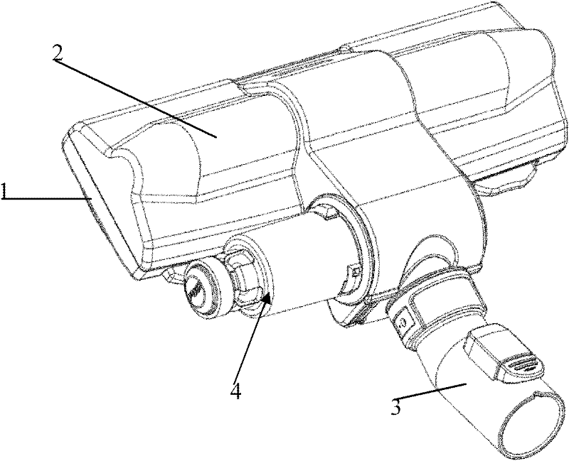
[0026] The suction head of the vacuum cleaner of the present invention is composed of a rectangular bottom shell and an upper cover. The connected telescopic dust suction pipe is connected, and the bottom surface of the bottom shell is provided with a suction nozzle. When in use, the vacuum motor works after the current is introduced, and the dust on the cleaning surface enters the suction head of the vacuum cleaner through the suction nozzle on the bottom of the bottom shell, and enters the...


PUM


Abstract

The invention discloses a dust display which comprises a display cavity, wherein the display cavity is communicated with an air inlet pipe and an air outlet pipe and is made of a transparent material; and in addition, the display cavity comprises a cylindrical shell and an internal cavity fixedly connected with the shell, an inflow part and a conical flow guide part are formed at two ends of the internal cavity, and an opening structure is arranged at the end part of the conical flow guide part. The dust display also comprises a cup shield which is detachably and fixedly connected to the end part of the display cavity and accommodates the conical flow guide part. The dust display provided by the invention is provided with an independent internal cavity structure and is capable of effectively improving the rotating force and effectively separating dust from air flow; simultaneously the inlet pipe of the dust display is directly connected with the internal cavity, thereby achieving a more sensitive display effect that a very small amount of dust also can be displayed; and an outer square hole at the end part of the cup shield is communicated with the outside, so that dust at corners can be cleared up very well and no dust can be left.

Description

technical field [0001] The invention relates to a vacuum cleaner; in particular, it relates to a dust display for the suction head of the vacuum cleaner. Background technique [0002] Generally, a vacuum cleaner is a device that uses a vacuum to generate suction to inhale air, make the air flow through various filters, filter foreign objects in the air, and clean the room. [0003] Generally speaking, a vacuum cleaner mainly includes a suction device and a suction pipeline. The suction device mainly formed by a motor and a fan is arranged in the body. The suction pipeline includes a suction head and a suction pipe. The suction head has a downward opening. The suction port communicates with the air inlet of the fan inside the body through the telescopic pipe and the flexible pipe of the suction pipe. When the vacuum cleaner is running, the motor drives the impeller of the fan to rotate at a high speed, exhausting the air in the vacuum cleaner, forming an instantaneous vacuum...

Claims


Application Information

Patent Timeline
IPC IPC(8): A47L9/00A47L9/19
Inventor 肖宗亮
Owner NANJING LG PANDA APPLIANCES
Why Eureka
Try Eureka