Rod placing device

A bar and bar technology, applied in the field of bar placement devices, can solve the problems of high labor intensity and low work efficiency of workers, and achieve the effects of simple structure, satisfying configuration requirements, and realizing process mechanization and automation.

Inactive Publication Date: 2012-05-16
KEDA INDUSTRIAL GROUP CO LTD
View PDF7 Cites 3 Cited by
  • Summary
  • Abstract
  • Description
  • Claims
  • Application Information

AI Technical Summary

Problems solved by technology

However, the work of placing these rods must be done manually by a special person, and the labor intensity of the workers is high, and the work efficiency is low.

Method used


Image

  • Rod placing device
  • Rod placing device
  • Rod placing device

Examples


Embodiment Construction

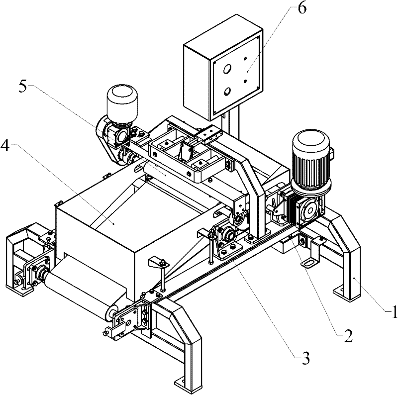
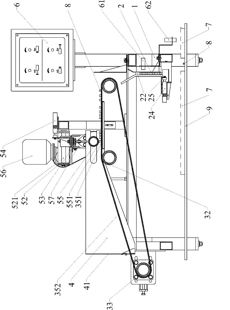
[0025] like Figure 2 to Figure 7 As shown, a rod placing device according to the present invention is tied to a frame 1 to set a rod blanking mechanism 2, a rod conveying mechanism 3, a feed bin 4, a lever mechanism 5 and an electric control device 6.

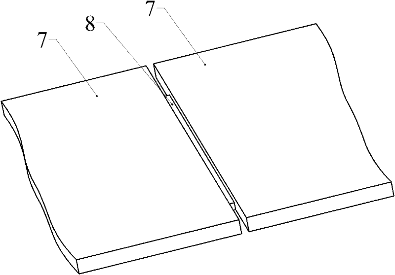
[0026] like image 3 , Image 6 and Figure 7 As shown, the bar blanking mechanism 2 includes a vertically arranged first bar 211 and a second bar 212, wherein the first bar 211 is connected to the frame 1 through a fixed connection, and the second bar The bar 212 is connected with the frame 1 in an adjustable manner. The gap between the two bars forms a bar channel 22, because the second bar 21 is adjustable, so the width S1 of the bar channel 22 is also adjustable, and the width S1 should be greater than or equal to the width of a bar and less The width of the two rods is preferably slightly wider than the width of one rod by 1-2mm. Therefore, the rods 8 placed in the rod channel 22 are stacked single from bottom to top....


PUM


Abstract

The invention discloses a rod placing device. the rod placing device is provided with a machine frame, wherein a rod discharging mechanism and a rod conveying mechanism are arranged on the machine frame, the rod discharging mechanism comprises a rod passageway, the width S1 of the rod passageway is larger than or equal to the width of one rod but smaller than the width of two rods, a horizontal supporting surface and a lower outlet are arranged below the rod passageway, the height S2 of the lower outlet is larger than or equal to the height of one rod but smaller than the height of two rods, a pushing mechanism is arranged at one side of the horizontal supporting surface, and corresponds to the lower outlet of the rod passageway, a rod outlet is arranged at the other side of the horizontal supporting surface, and is arranged above a tile conveying path, and an output end of the rod conveying mechanism is correspondingly arranged above an upper inlet of the rod passageway. By adopting the rod placing device disclosed by the invention, the mechanization and automation of rod placing processes can be realized, and configuration requirements of a high-output polished ceramic tile production line are met; and moreover the rod placing device is simple and reliable in structure.

Description

technical field [0001] The invention belongs to the field of deep processing machinery for ceramic polished tiles, and in particular relates to a rod placement device for placing rods for separating two ceramic tiles. Background technique [0002] At present, when the surface of ceramic polished tiles is deep processed, due to the height difference between the polished tiles, it is difficult to guarantee the polishing quality of the surface near the edge of the polished tiles; product quality. like figure 1 As shown, usually the simple and effective way to solve the above problems is to place a bar 8 between the bricks 7 and 7 so that a certain distance is kept between the bricks. However, the work of placing these rods needs to be done manually by a special person, and the labor intensity of the workers is high, and the work efficiency is low. Contents of the invention [0003] The object of the present invention is to provide a rod placement device with simple structu...

Claims


Application Information

Patent Timeline
Patent Type & Authority Applications(China)
IPC IPC(8): B24B55/00
Inventor 陈光永
Owner KEDA INDUSTRIAL GROUP CO LTD
Why Eureka
Try Eureka