Air channel ignition system and ignition burner under bed

An under-bed ignition and burner technology, applied in the direction of burners, fluidized bed combustion equipment, burners burning powder fuel, etc., can solve the problems of fuel waste, cumbersome debugging process, oil dripping, etc., and achieve simplified start-up and The effect of debugging process, reducing fuel consumption and avoiding fuel waste

Active Publication Date: 2012-05-16
YANTAI LONGYUAN POWER TECH
View PDF6 Cites 6 Cited by
  • Summary
  • Abstract
  • Description
  • Claims
  • Application Information

AI Technical Summary

Problems solved by technology

During the start-up and commissioning process of the circulating fluidized bed boiler, it is necessary to adjust the atomizing sheet several times to improve the atomization effect of the fuel oil, which makes the starting and debugging process of the circulating fluidized bed boiler very c

Method used


Image

  • Air channel ignition system and ignition burner under bed
  • Air channel ignition system and ignition burner under bed
  • Air channel ignition system and ignition burner under bed

Examples


Embodiment 1

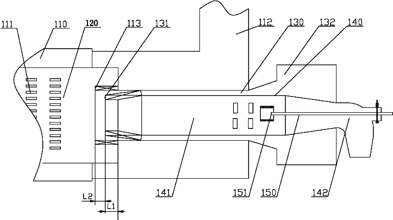
[0037] Please refer to figure 2 , which is a schematic structural diagram of an under-bed ignition burner provided in Embodiment 1 of the present invention. The under-bed ignition burner includes a supplementary air passage 110, a combustion air duct 120 and an air distribution duct 130; The duct 110 communicates with a predetermined air source through the supplementary air opening 112 . The rear end of the air distribution channel 130 forms a peripheral air nozzle 131 which communicates with the front end of the combustion air channel 120 , and the front part of the air distribution channel 130 communicates with a predetermined air source through an air distribution port 132 . In addition, the under-bed ignition burner also includes a burner body 140 and an ignition device 150 . The burner body 140 includes an internal combustion section 141; the front end of the internal combustion section 141 communicates with a predetermined pulverized coal passage (not shown in the fig...

Embodiment 2

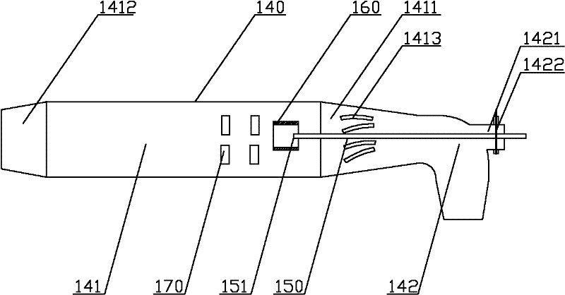
[0052] Please refer to Figure 4 , which is a schematic structural diagram of the under-bed ignition burner provided in Embodiment 2 of the present invention. Compared with Embodiment 1, the difference lies in that: the ignition device 150 is an oil gun assembly that consumes fuel; the oil gun assembly includes an oil gun and an air distributor used in conjunction with the oil gun. The ignition end formed by the oil gun assembly extends into the front end of the internal combustion section 141 . Same as the first embodiment, the oil gun assembly is movably installed in the burner body. Such as Figure 5As shown, this figure is a structural schematic diagram of another state of the under-bed ignition burner provided by Embodiment 2 of the present invention. When the ignition device 150 is an oil gun assembly, when there is a problem with the pulverized coal supply or other circumstances, the ignition device under the bed can be easily changed so that the oil gun assembly can...


PUM


Abstract

The invention discloses an ignition burner under a bed and an air channel ignition system. The disclosed ignition burner under the bed comprises an air replenishing channel, a burning air channel and an air distribution channel, the air replenishing channel is communicated with the burning air channel, the back end of the air distribution channel is communicated with the front end of the burning air channel, the ignition burner also comprises a burner body and an ignition device with an ignition end which stretches into the burner body; an internal combustion segment is formed in the burner body, the front end of the internal combustion segment is communicated with a pulverized coal channel, and the back end of the internal combustion part is communicated with the front end of the burningair channel. Compared with the prior art, in the ignition burner under the bed, bed material is heated by the heat which is generated by burning of pulverized coal, thereby realizing the start of a circulating fluidized bed boiler, and the fuel oil consumption during the start of the circulating fluidized bed boiler can be reduced.

Description

technical field [0001] The invention relates to a boiler ignition technology, in particular to an under-bed ignition burner, and an air duct ignition system including the under-bed ignition burner, which is used for starting a circulating fluidized bed boiler. Background technique [0002] At present, China is the country with the largest number of circulating fluidized bed (CFB) boiler generator sets, the largest total installed capacity and the fastest development speed in the world. At present, more than 3,600 circulating fluidized bed boiler generator sets have been put into use, with a maximum unit capacity of 600MW; the total installed capacity is about 70-80 million kilowatts. Among them, more than 200 circulating fluidized bed boiler generator sets of 135-150MW (440-480t / h) have been put into operation and are planned to be built; 300MW circulating fluidized bed generator sets have been put into operation and are planned to be built Also more than 60 units. [0003...

Claims


Application Information

Patent Timeline
IPC IPC(8): F23D1/00F23D1/02F23C10/18
Inventor 程昌业董永胜刘欣王晓建王新光付玉玲
Owner YANTAI LONGYUAN POWER TECH
Why Eureka
Try Eureka