Working liquid and device utilizing same

An in-device, working fluid technology, used in transmission, fluid transmission, petroleum industry, etc., can solve problems such as corrosion and abnormal noise, and achieve the effect of suppressing size

Active Publication Date: 2012-05-16
BRIDGESTONE CORP
View PDF4 Cites 0 Cited by
  • Summary
  • Abstract
  • Description
  • Claims
  • Application Information

AI Technical Summary

Problems solved by technology

Therefore, there may occur such as abnorma

Method used


Image

  • Working liquid and device utilizing same
  • Working liquid and device utilizing same
  • Working liquid and device utilizing same

Examples


Embodiment Construction

[0029] A working fluid according to one embodiment of the present invention will be described below.

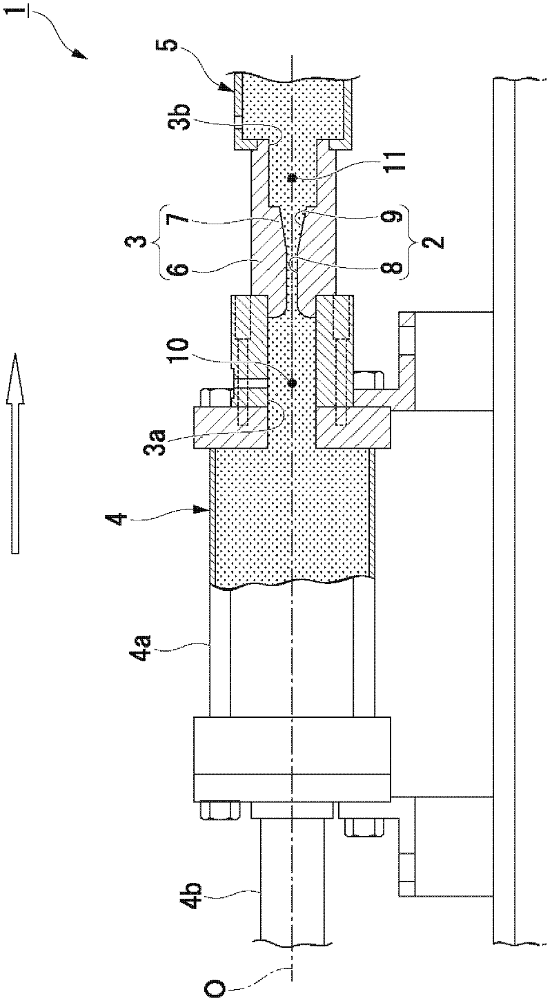
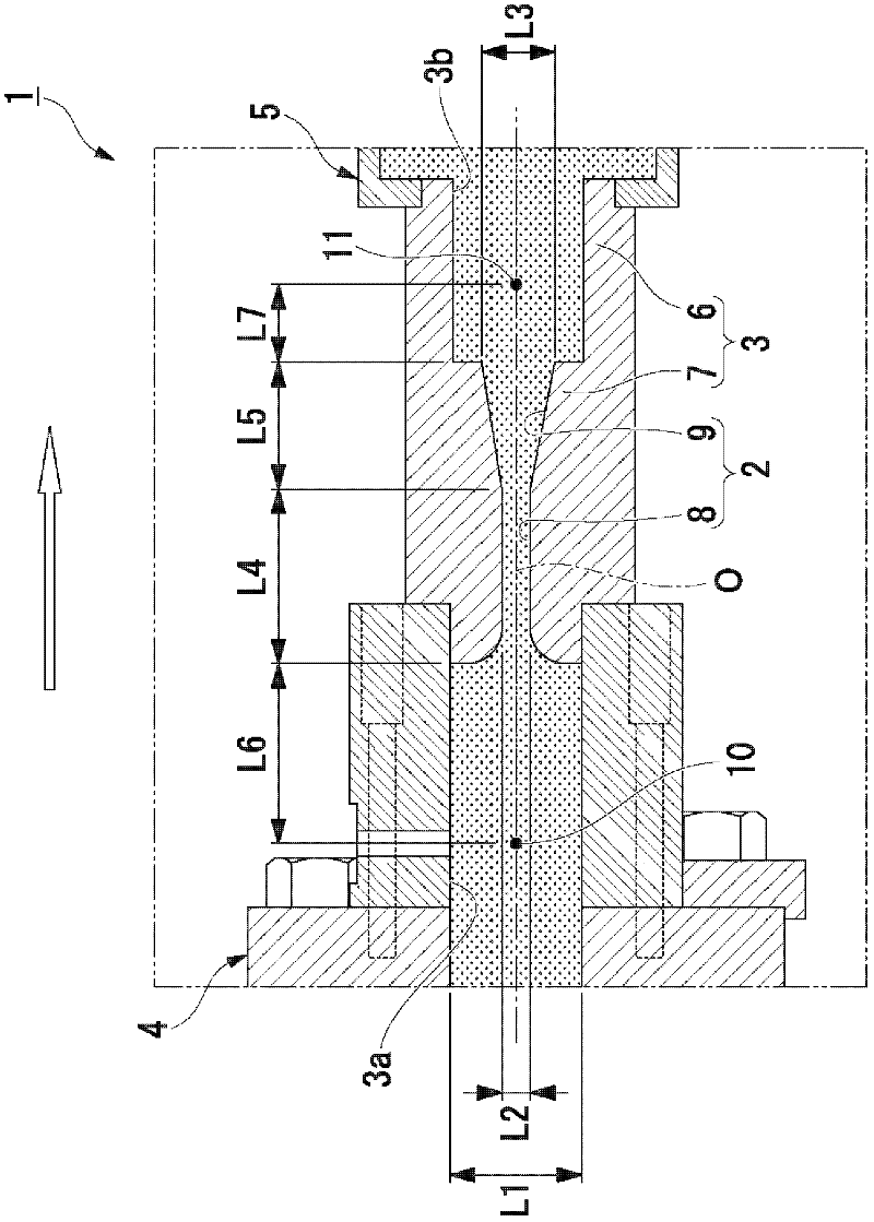
[0030] The working fluid of the present embodiment is used by being sealed in the liquid sealing space in the device. In addition, the working fluid of the present embodiment plays a role of transferring energy such as kinetic energy or thermal energy in the device, absorbing and weakening a load applied from the outside of the device, and the like, for example. And, in the device in which the working fluid is sealed in the liquid sealing space, the function required for the device is exhibited based on the above-mentioned action of the working fluid.

[0031] This working fluid is suitable for the following cases, etc.: For example, working oil sealed in an ink pressurizing mechanism of an inkjet printer, various hydraulic devices, etc., and flowing inside the device to transmit kinetic energy; sealing a liquid crystal for cooling a liquid crystal projector; Heat medium (su...


PUM

PropertyMeasurementUnit
Dynamic viscosityaaaaaaaaaa

Abstract

A working liquid which is intended to be encapsulated in a liquid-encapsulating space in a device upon use, and which comprises a first liquid and a second liquid insoluble in each other, wherein the second liquid is contained in an amount smaller than that of the first liquid by weight and exhibits a higher steam pressure than that of the main component of the first liquid at the same temperature.

Description

technical field [0001] The present invention relates to a working fluid used in a liquid-enclosed space enclosed in a device. This application claims the priority of Japanese Patent Application No. 2009-144620 for which it applied in Japan on June 17, 2009, and uses the content in this specification. Background technique [0002] It has been well known that, for example, in the vibration isolation device shown in the following patent document 1, the ink pressurizing mechanism of the inkjet printer shown in the patent document 2, etc., the working fluid is sealed in the whole device used in the liquid sealing space, when the liquid sealing When the hydraulic pressure in the space drops sharply, cavitation occurs in the working fluid in which air bubbles are generated. [0003] Patent Document 1: Japanese Patent Application Laid-Open No. 60-34541 [0004] Patent Document 2: Japanese Patent Application Laid-Open No. 5-64897 [0005] If cavitation occurs, then when the hydrau...

Claims


Application Information

Patent Timeline
IPC IPC(8): C10M111/00F16F13/08F16H41/32C10M105/14C10M107/38C10M107/50C10N30/00C10N30/18C10N40/08
CPCF16H41/32C10M2207/0203F16F9/34C10M111/02C10M2213/003C10M2207/0225C10M2207/103C10N2230/18F16F9/006C10M2229/025C10M2211/0425C10N2240/08C10M111/04C10N2030/18C10N2040/08
Inventor 植木哲长岛康寿之栁田基宏铃木康弘石山达郎田代胜巳
Owner BRIDGESTONE CORP
Why Eureka
Try Eureka