Multi-membrane reservoir sealing test
A leak detection and cabin technology, applied in container discharge methods, fluid tightness testing, container filling methods, etc., can solve problems such as difficult to find optical camera thermometers
- Summary
- Abstract
- Description
- Claims
- Application Information
AI Technical Summary
Problems solved by technology
Method used
Image

Examples
Embodiment Construction
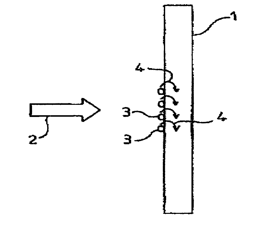
[0039] figure 1 Bulkhead 1 is depicted and the mean temperature of the bulkhead is TM. At pressure P the gas comes into contact with the bulkhead 1 as indicated by arrow 2 . If the condensation temperature TC of the gas is higher than the temperature TM, the gas will condense in the form of liquid or solid precipitate 3 . According to this mode, the gas condenses and releases latent heat which is transferred to the bulkhead 1 . This thermal energy transfer is indicated by arrow 4, therefore, the local temperature T of the bulkhead 1 will be higher than TM. When the temperature TM, pressure P and the nature of the gas are controllable, the condensation at this time is called forced condensation.
[0040] Such gases may be:
[0041] A single gas whose inherent physical properties correspond to the ideal condensation temperature.
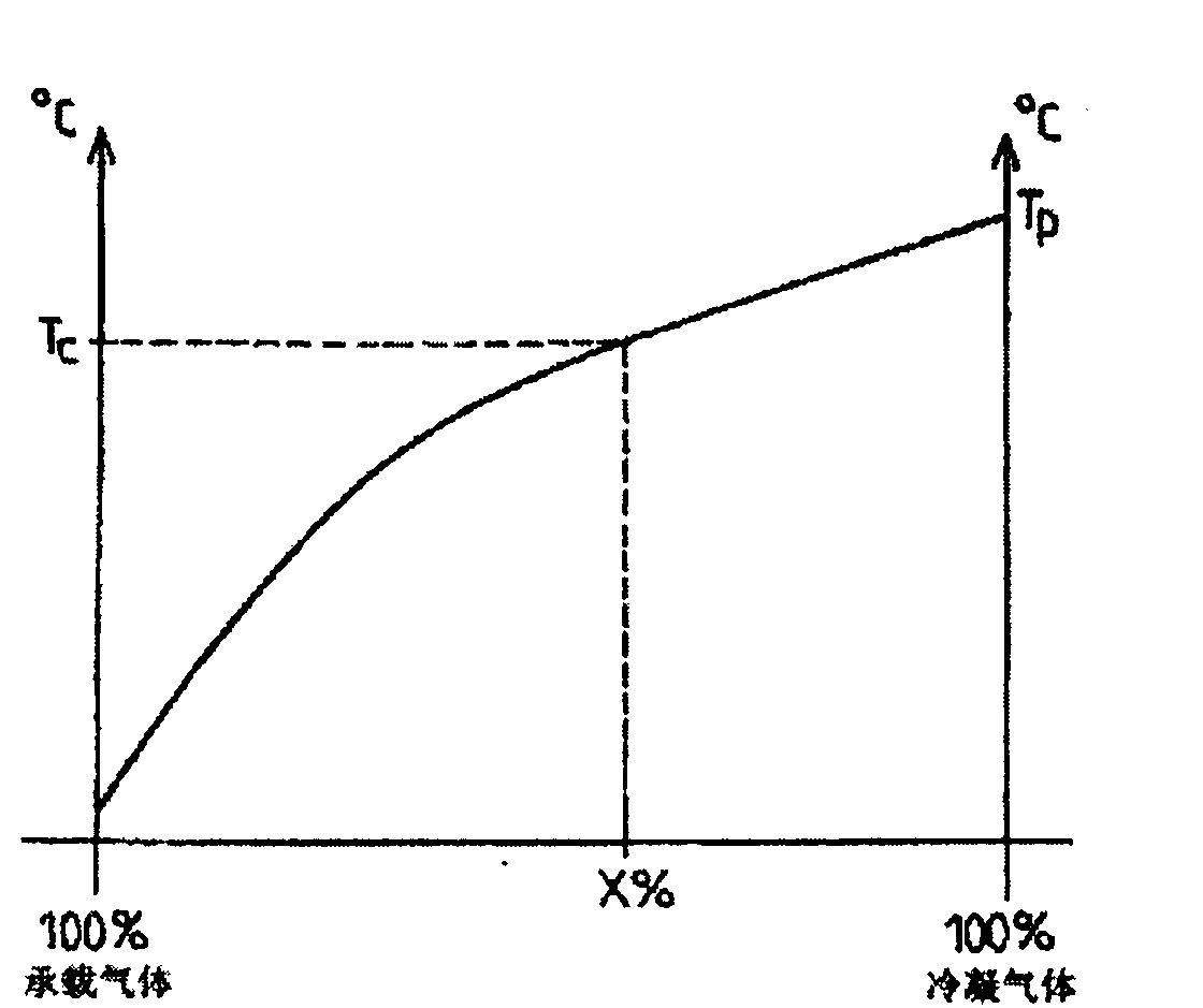
[0042] A mixture of noncondensable and condensable gases whose concentration can be adjusted to suit the condensation temperature. Specifically,...
PUM
| Property | Measurement | Unit |
|---|---|---|
| Average temperature | aaaaa | aaaaa |
Abstract
Description
Claims
Application Information
PatSnap Eureka turns technology decisions into work you can execute. Powered by our Innovation Knowledge Graph, it runs expert workflows across engineering, life sciences, materials and intellectual property. Get your review-ready output in minutes.


