
Heating bed, heating method and medical system

A heating unit and heating cycle technology, applied in the field of medical systems, can solve problems such as affecting imaging quality, and achieve the effect of improving comfort

Inactive Publication Date: 2012-05-23
GE MEDICAL SYST GLOBAL TECH CO LLC
View PDF6 Cites 1 Cited by
  • Summary
  • Abstract
  • Description
  • Claims
  • Application Information

AI Technical Summary

Problems solved by technology

But doing so will increase the additional object-to-image distance (OID) and affect the final image quality, so it is not recommended

Method used


Image

  • Heating bed, heating method and medical system
  • Heating bed, heating method and medical system
  • Heating bed, heating method and medical system

Examples


Embodiment Construction

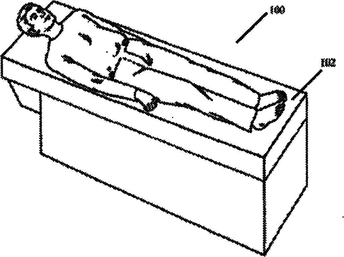
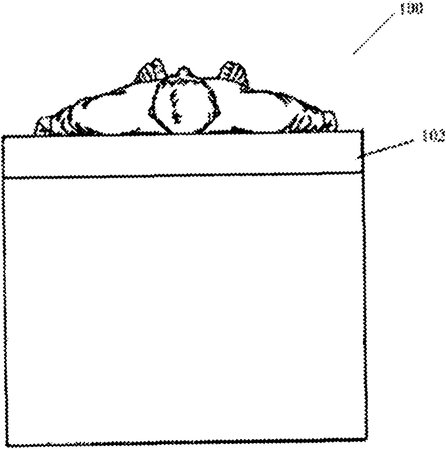
[0023] figure 1 and figure 2 An embodiment of the heated bed of the present invention is shown. As shown, heated bed 100 includes a bed surface 102 . During radiographic diagnosis, the patient usually lies on the bed surface 102 .

[0024] exist figure 1 and figure 2 In , the bed surface 102 is shown to be rectangular. However, those skilled in the art can easily understand that the shape of the bed surface is not limited to a rectangle, and can be any suitable shape, such as an ellipse.

[0025] In the description of this specification, the term "heated bed" is used to indicate a bed with a heating function. In addition, terms such as "heated bed surface" and "bed surface" are also used in the description to indicate the surface of the "heated bed". Furthermore, the meaning of the term "bed" is not limited to a bed in the general sense of the surface fixed and parallel to the ground (as shown). In one embodiment of the present invention, the surface of the heating b...


PUM

PropertyMeasurementUnit
thermal conductivityaaaaaaaaaa

Abstract

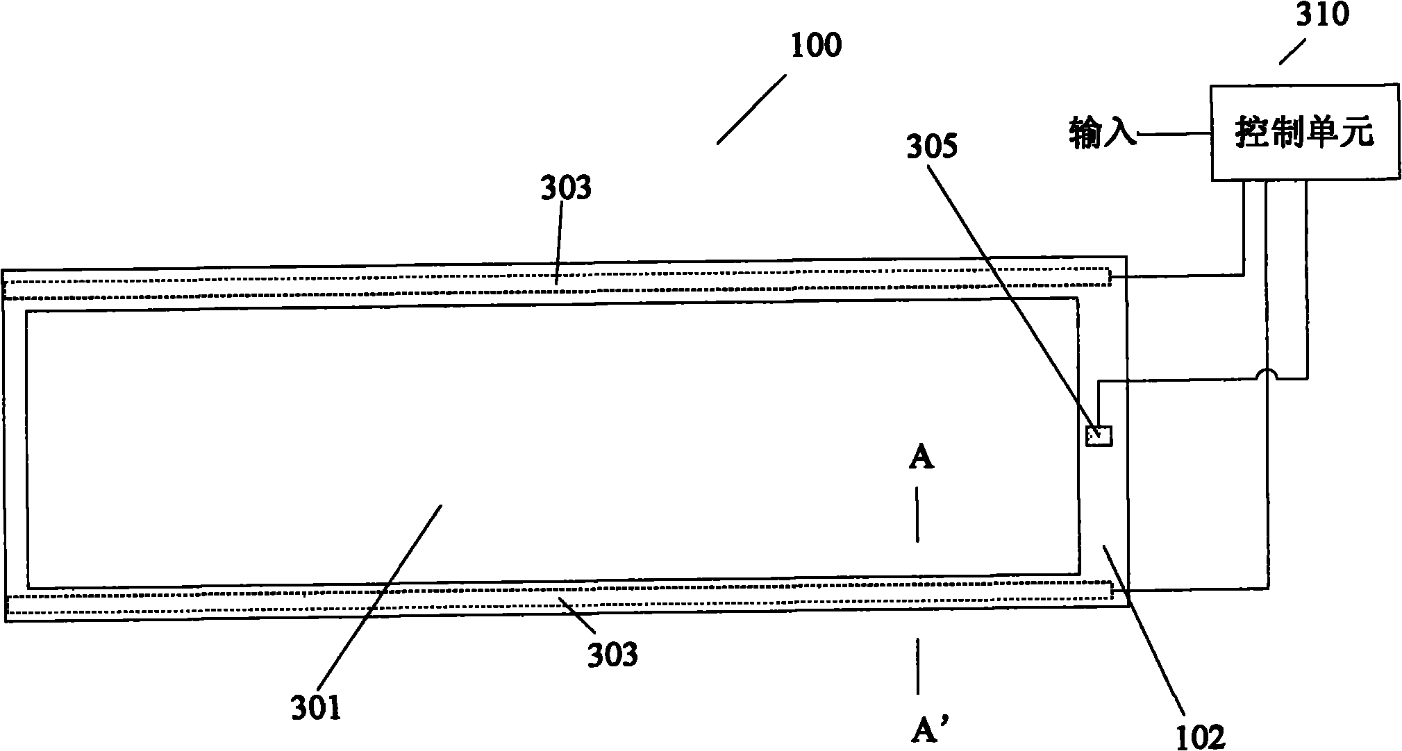
The invention provides a heating bed 100 for ray diagnosis. The heating bed 100 comprises a bed surface 102, wherein the bed surface 102 comprises a heating unit 303 arranged on the axial edge of the bed surface 102, and a carbon fiber composite material layer 402; and the heating unit 303 is coupled with the carbon fiber composite material layer 402, so that a patient cannot feel cold and uncomfortable when lying on the heating bed. The invention also provides a heating method and a medical system with the heating bed.

Description

technical field [0001] The present invention relates to a heated bed, a heating method, and a medical system including the heated bed. Background technique [0002] X-rays can penetrate substances that ordinary visible light cannot. Because of the long wavelength of visible light, the energy of its photons is very small. When the visible light hits an object, part of it is reflected and most of it is absorbed by the material, so it cannot pass through the object. This is not the case with X-rays. Because of their short wavelength and high photon energy, when they shine on a substance, only a part is absorbed by the substance, and most of them pass through the interatomic gap, showing a strong penetrating ability. The X-ray penetrating ability is related to the density of the material. The denser material absorbs more X-rays and transmits less; the material with lower density absorbs less X-rays and transmits more. Using the nature of differential absorption of X-rays, soft...

Claims


Application Information

Patent Timeline
Patent Type & Authority Applications(China)
IPC IPC(8): A61B19/00A61B6/00H05B3/06
CPCA61B6/0442H05B1/025A61B6/045H05B3/20A61F2007/0095H05B2203/033A61F7/007
Inventor 王锋李玉庆李富生
Owner GE MEDICAL SYST GLOBAL TECH CO LLC
Learn More