
Shredder

A paper shredder and paper guide mechanism technology, which is applied to grain processing and other directions, can solve the problems of large paper particles, low paper shredding efficiency, and failure to meet the destruction standards of primary shredders, and achieves comprehensive paper shredding and uniform particles , the effect of simple operation

Active Publication Date: 2012-05-23
BEIJING HESHENGDA INFORMATION SECURITY TECH
View PDF8 Cites 19 Cited by
  • Summary
  • Abstract
  • Description
  • Claims
  • Application Information

AI Technical Summary

Problems solved by technology

Although these two types of shredders can achieve the purpose of shredding paper, their shredding efficiency is not high, and they cannot meet the standard of first-class shredders, that is, all the shredded paper particles cannot reach the standard of less than 1mm×2mm
The paper particles crushed by this one-time crushing type paper shredder are relatively large, generally larger than 1mm×2mm, which cannot meet the standard of the first-class paper shredder
Due to the defect in the connection structure between the strip knife and the spiral knife of the paper shredder of the double-shredding type, most of the front of the paper can be crushed into paper particles smaller than 1mm×2mm, but the final paper particles with a length of about 15mm Some parts cannot be cut, but form 2mm×15mm long strip particles, and there is a crushing dead angle. Therefore, the paper shredder of this double crushing type cannot meet the standard of the first-class shredder, and does not meet the requirements of the first-class destruction standard of the State Secrets Bureau
That is to say, as of now, there is no paper shredder on the market that can meet the national first-level destruction standard. Even some brand paper shredders claim to be able to crush into 1mm×1mm particles, but because the crushed particles are mixed with Contains many large particles and therefore does not qualify for primary shredder destruction

Method used


Image

  • Shredder
  • Shredder
  • Shredder

Examples


Embodiment Construction

[0017] The present invention will be described in detail below in conjunction with the accompanying drawings.

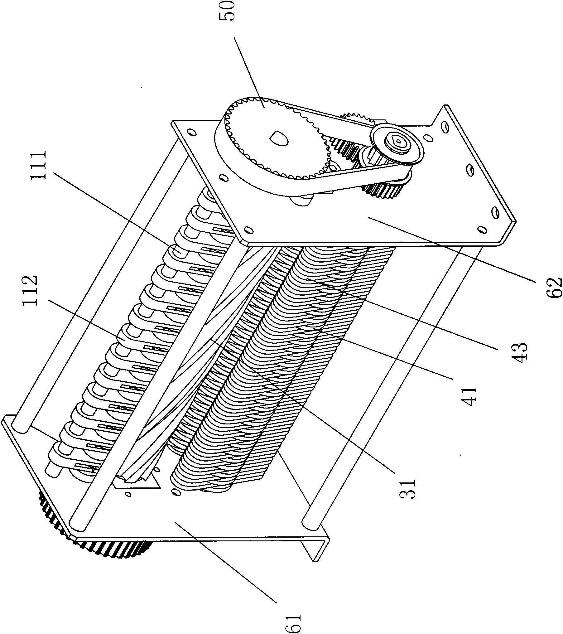
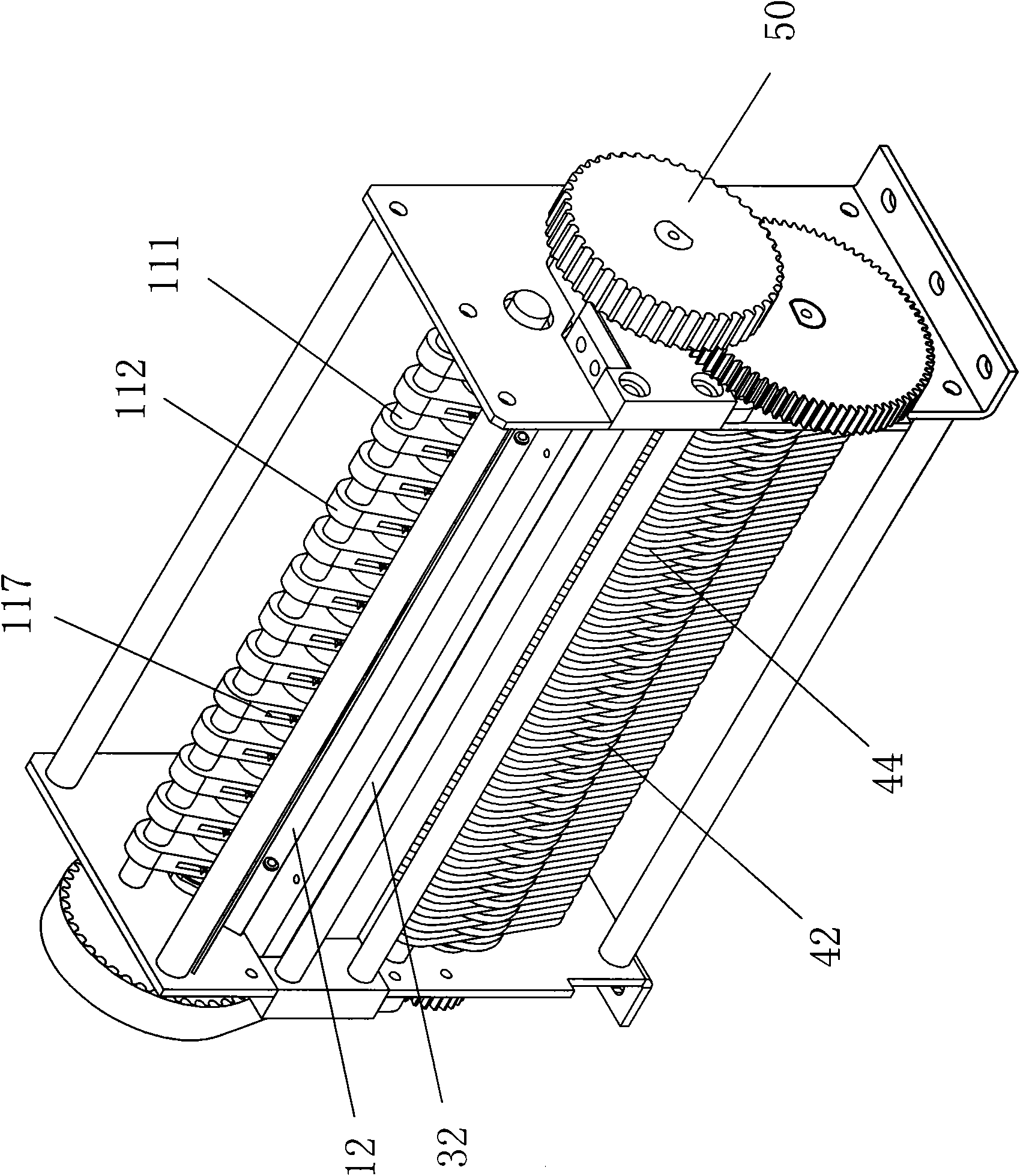
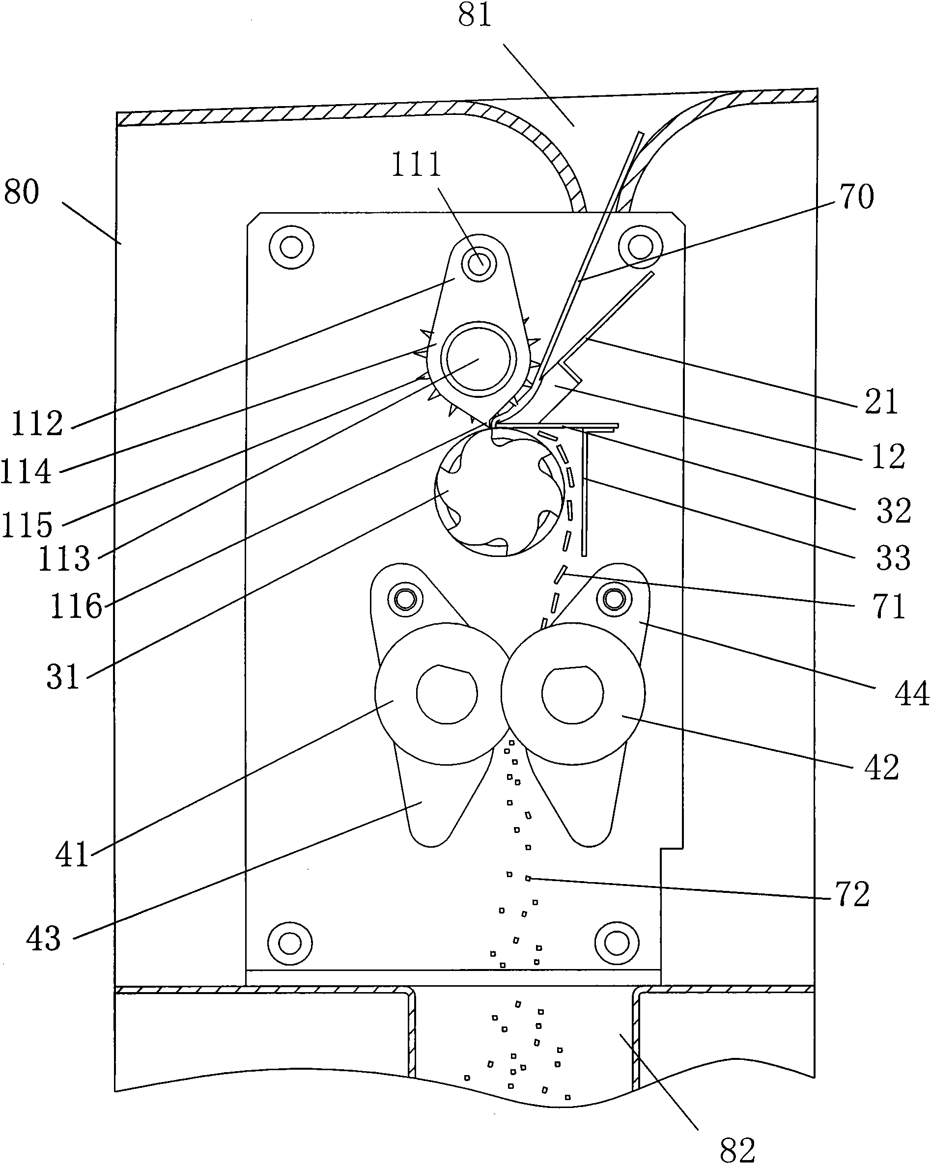
[0018] Such as Figure 1 to Figure 6 As shown, the paper shredder of the present invention includes a casing 80, the top and bottom of the casing 80 are respectively provided with a paper inlet 81 and a paper outlet 82, and a paper guide mechanism for rolling in and conveying the paper 70 is installed in the casing 80 , a horizontal paper cutting mechanism for cutting the paper 70 into horizontal strips 71 and a vertical paper cutting mechanism for cutting the horizontal strips 71 into particles 72, the horizontal paper cutting mechanism is located below the paper guide mechanism, the The vertical paper cutting mechanism is located below the horizontal paper cutting mechanism. The paper guide mechanism, the horizontal paper cutting mechanism and the vertical paper cutting mechanism are all connected to the transmission mechanism 50. The paper inlet 81 is set correspo...


PUM


Abstract

The invention discloses a shredder, comprising a housing. A paper inlet and a paper outlet are respectively arranged on top and bottom of the housing. A paper guiding mechanism for drawing and conveying paper, a transverse paper cutting mechanism for cutting paper into transverse strips and a vertical paper cutting mechanism for cutting the transverse strips into particles are arranged in the housing. The transverse paper cutting mechanism is arranged under the paper guiding mechanism; the vertical paper cutting mechanism is arranged under the transverse paper cutting mechanism; the paper guiding mechanism, the transverse paper cutting mechanism and the vertical paper cutting mechanism are all connected with a transmission mechanism; the paper inlet is arranged corresponding to the paper guiding mechanism, and the paper outlet is arranged corresponding to the vertical paper cutting mechanism. The shredder of the invention can crush paper into small particles rapidly and carry out effective crushing and destroy on paper, and is simple and convenient for operation.

Description

technical field [0001] The invention relates to a crushing mechanism, especially a paper shredder. Background technique [0002] According to the State Secrets Bureau BMB21-2007 "Safety and Confidentiality Requirements for Carrier Destruction and Information Elimination Involving State Secrets", the paper shredders used by state secrets-related units must meet the first-level destruction standard, that is: all paper shredded particles must be less than 1mm× 2mm. [0003] At present, the existing paper shredders on the market mainly include one-time shredding type and two-time shredding type. One-shot shredders use a set of knives to shred paper into larger particles. The double shredding type paper shredder adopts a two-layer structure. A pair of strip knives on the first layer cuts the paper into vertical strips, and then the vertical strips are cut into particles by the second layer of spiral knives. Although these two types of shredders can achieve the purpose of shred...

Claims


Application Information

Patent Timeline
Patent Type & Authority Applications(China)
IPC IPC(8): B02C18/14B02C18/18B02C18/22
Inventor 王恬恬魏振家赵龙杨勇
Owner BEIJING HESHENGDA INFORMATION SECURITY TECH
Learn More