Method for accurately positioning electronic tag

A technology of precise positioning and electronic labeling, applied in positioning, radio wave measurement systems, measurement devices, etc., can solve problems such as less research, and achieve the effect of simple operation principle, small amount of calculation, and excellent real-time performance.

Inactive Publication Date: 2012-05-23
ZHEJIANG OCEAN UNIV
View PDF3 Cites 6 Cited by
  • Summary
  • Abstract
  • Description
  • Claims
  • Application Information

AI Technical Summary

Problems solved by technology

At present, the domestic research on RFID mainly focuses on the intermediate frequency system with a working frequency of about 13.56MHz, and there is less research in the field of UHF.

Method used


Image

  • Method for accurately positioning electronic tag
  • Method for accurately positioning electronic tag
  • Method for accurately positioning electronic tag

Examples


Embodiment Construction

[0020] The present invention will be further described in detail below in conjunction with the accompanying drawings and embodiments.

[0021] An electronic tag precise positioning algorithm, the specific steps are:

[0022] 1. Establish the antenna array of the RF signal detector in three-dimensional space

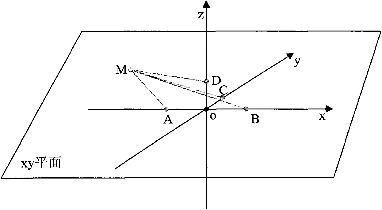
[0023] Such as figure 1 As shown, in three-dimensional space, it is assumed that there is a passive electronic tag at any point M. There is a radio frequency signal detector within the effective detection range. The antenna of the instrument is an array antenna, and the tops of each antenna are arranged according to the four points A, B, C, and D in Figure 1, where AO=OB=mλ, OC=nλ, OD=kλ, λ is the radio frequency wavelength and AO, OB, OC, and OD are fixed values, and point M is the location of the hypothetical electronic tag.

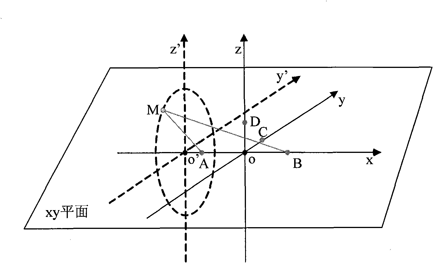
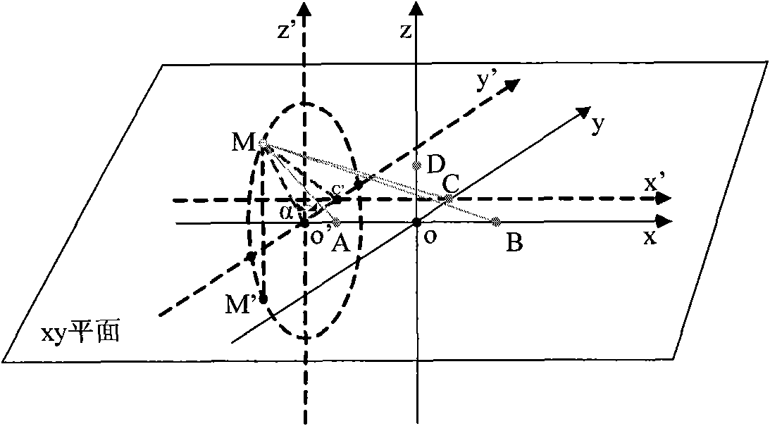
[0024] 2. Locate the three-dimensional space to the two-dimensional plane, and determine the M value range

[0025] RF signal detector at t ...


PUM


Abstract

The invention discloses a method for accurately positioning an electronic tag, comprising steps of: firstly establishing an antenna array of a radio-frequency signal detector; positioning the electronic tag to a two-dimensional plane from a three-dimensional space through a four-point positioning method; and then in combination with a trigonometric function algorithm, positioning the electronic tag to a 1 / 2 two-dimensional plane from the two-dimensional plane, further positioning the electronic tag to a 1 / 4 two-dimensional plane from the 1 / 2 two-dimensional plane, at last accurately positioning the electronic tag at the 1 / 4 two-dimensional plane. The positioning algorithm provided by the invention has the advantages of simple operation principle, small calculation amount, good instantaneity, and high positioning accuracy, and can be applied to a situation in which the electronic tag is accurately positioned.

Description

technical field [0001] The invention relates to the technical field of passive electronic tag positioning, in particular to a method of applying radio frequency identification technology (RFID) in combination with radio wave propagation characteristics, and realizing precise positioning of electronic tags through a positioning algorithm. Background technique [0002] Radio frequency identification technology (RFID) is an automatic identification technology that began to emerge in the 1990s. It uses radio frequency signals to achieve non-contact information transmission through spatial coupling (alternating magnetic field or electromagnetic field), and achieves the purpose of identification through the transmitted information. The frequencies of the RFID system mainly include 125kHz, 13.56MHz, 900MHz, 2.45GHz, and 5.8GHz. At present, domestic RFID research mainly focuses on the intermediate frequency system with a working frequency of about 13.56MHz, and there is less researc...

Claims


Application Information

Patent Timeline
IPC IPC(8): G01S5/06
Inventor 赵秋亮范细秋胡佳文
Owner ZHEJIANG OCEAN UNIV
Why Eureka
Try Eureka