Slide fastener

A technology of zipper and zipper teeth, which is applied in the direction of sliding fastener components, applications, fasteners, etc., and can solve problems such as difficulty

Active Publication Date: 2012-05-23
YKK CORP
View PDF8 Cites 7 Cited by
  • Summary
  • Abstract
  • Description
  • Claims
  • Application Information

AI Technical Summary

Problems solved by technology

Passing the flange of the slider between the front stop and the front-most engaging element is not easy in practice and is likely to be an obstacle to the rapid separation of the zipper

Method used


Image

  • Slide fastener
  • Slide fastener
  • Slide fastener

Examples


Embodiment Construction

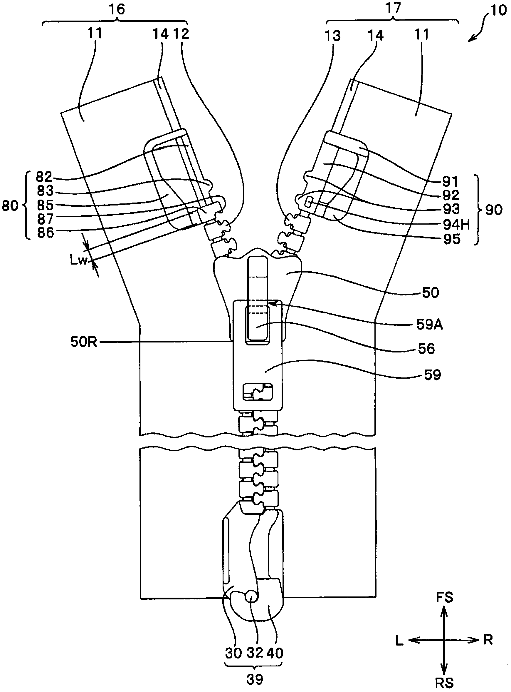
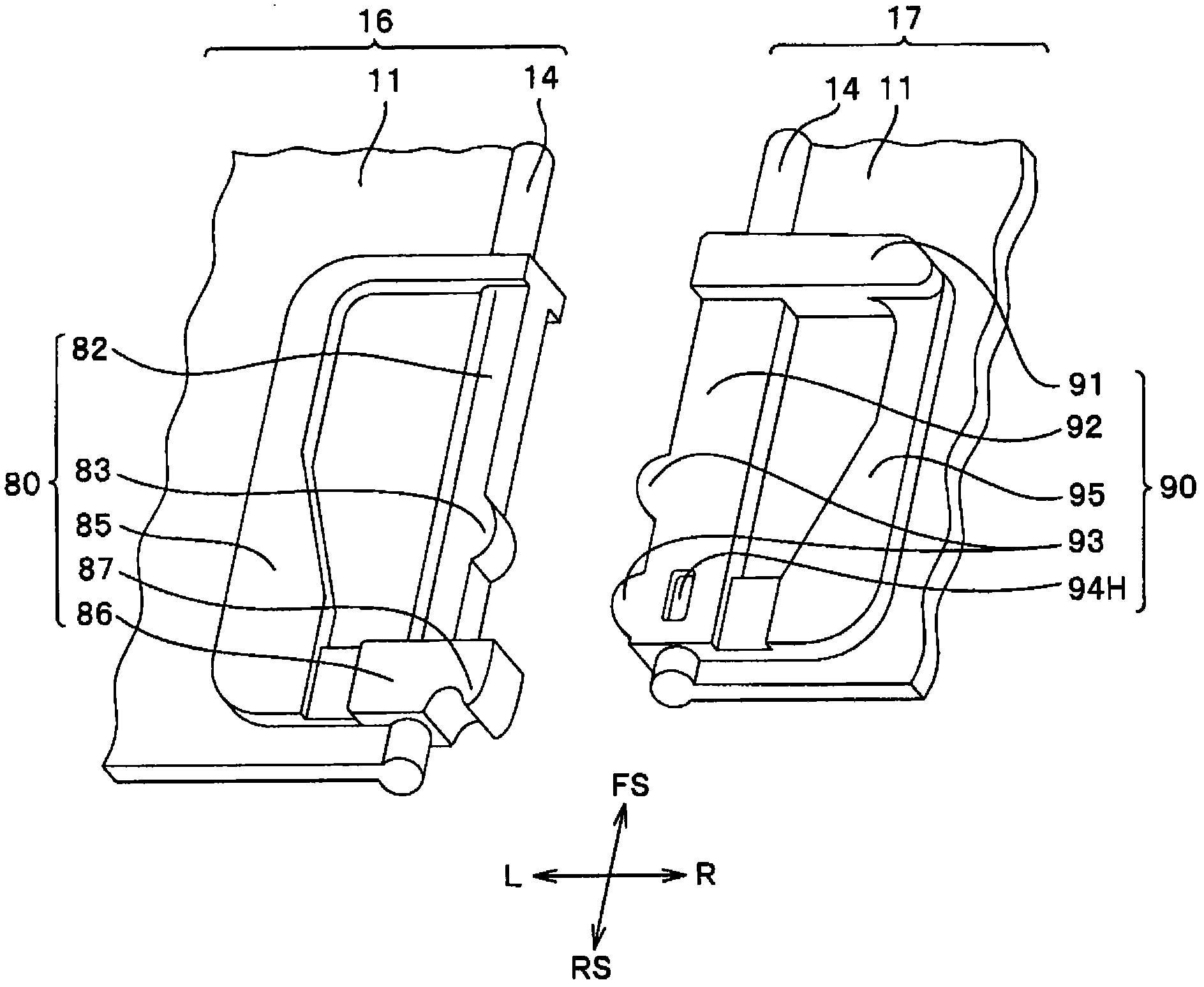
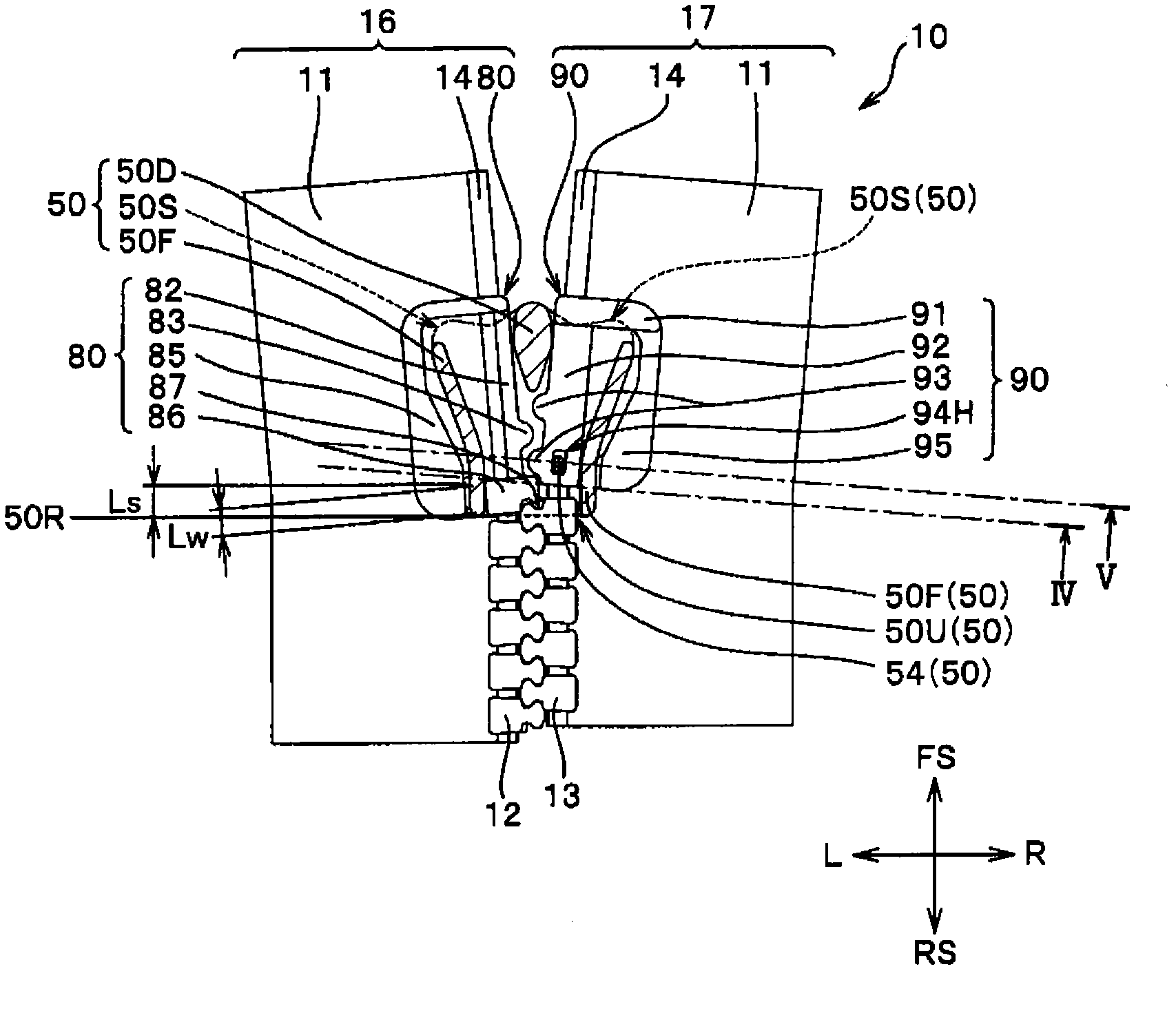
[0067] Below, while referring to the attached Figure 1 Typical examples of the slide fastener of the present invention will be specifically described. figure 1 It is a top view of the slide fastener 10 of this invention. figure 2 yes figure 1 The shown slide fastener 10 is a partially enlarged perspective view of the vicinity of the pull-out member 80 and the holding member 90 attached to the engaging slide end side of the first and second engaging elements 12 and 13 rows. image 3 In the state where the slide fastener 10 is closed by sliding the slider 50 to the engaging sliding end, the upper flap 52 of the slider 50 and the cut surface between the first and second zipper strings 16, 17 are closed. The slider 50 is cut and shows a top sectional view of the engaging element guide passage 50T. Figure 4 yes image 3 The sectional view shown in the direction of IV. Figure 5 yes image 3 The sectional view shown in the V direction.

[0068] Figure 1 to Figure 5 The s...


PUM


Abstract

A slide fastener (10) is provided with an extraction member (80) provided to a first fastener stringer (16) and also with a retaining member (90) provided to a second fastener stringer (17), and the extraction member (80) and the retaining member (90) are provided so as to face each other. The retaining member (90) is provided with a positioning section for positioning and holding a slider (50). The extraction member (80) is provided with a side-pull contact body (86). The side-pull contact body (86) comes in contact with a flange of a slider (50) when a side-pull force acts on the side-pull contact body (86), and the side-pull contact body (86) comes out of a rear opening of the slider (50) when the extraction member (80) is rotated and moved. This enables the slider (50) to be positioned and held at an engagement and sliding end. When the extraction member (80) is rotated in the direction in which the extraction member (80) is separated from the retaining member (90), the side-pull contact body (86) can be stably extracted from the rear opening of the slider (50) and the slide fastener can be easily set to an open state.

Description

technical field [0001] This invention relates to the slide fastener of a top open type which can make a slide fastener into an opened state without sliding operation of a slider. Background technique [0002] Conventionally, there is known a slide fastener in which a slide fastener in which a pair of left and right engaging element rows are in an engaged state can be instantaneously separated without performing a sliding operation of a slider. [0003] For example, a slide fastener with the following parts is disclosed in Japanese Publication No. 55-7135 (Patent Document 1): a pair of left and right zipper stringers, which are formed by disposing engaging element rows along the opposite end edges of the zipper strings; sliders, A pair of left and right engaging element rows are inserted through the engaging element guide passage of the slider, and the slider switches the engaging element row into an engaged state and a separated state by sliding along the engaging element ro...

Claims


Application Information

Patent Timeline
Patent Type & Authority Applications(China)
IPC IPC(8): A44B19/38A44B19/28A44B19/30
CPCA44B19/38A44B19/301
Inventor 高荷刚
Owner YKK CORP
Why Eureka
Try Eureka