
Method and apparatus for discharging liquid material, and program

A liquid material and discharge device technology, which is applied to the surface coating liquid device, spray device, spray device, etc., can solve the problems of particle generation, contamination of liquid material, deformation, etc., achieve stable discharge state, and improve discharge accuracy Effect

Active Publication Date: 2012-05-23
MUSASHI ENG INC
View PDF7 Cites 2 Cited by
  • Summary
  • Abstract
  • Description
  • Claims
  • Application Information

AI Technical Summary

Problems solved by technology

Since the sealing part is a sliding part, friction or deformation will occur, which will have various adverse effects on the pump.
For example, when there is friction, particles are generated that contaminate liquid materials and must be replaced frequently

Method used


Image

  • Method and apparatus for discharging liquid material, and program
  • Method and apparatus for discharging liquid material, and program
  • Method and apparatus for discharging liquid material, and program

Examples


Embodiment 1

[0076] (Structure of discharge device)

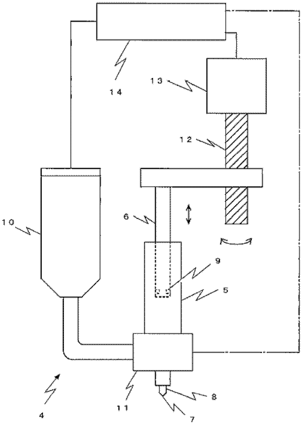
[0077] The discharge device of this embodiment refers to image 3 The following explanations are made. In addition, the liquid material used in this example is a liquid crystal (viscosity = about 20 mPa·s).

[0078] image 3 The shown discharge device 4 comprises: a tubular metering tube 5; a plunger 6 connected in the metering tube 5 with a sealing portion 9; a nozzle 8 having a discharge port 7; a storage container 10 for storing liquid materials; To switch the communication of the metering tube 5 and the nozzle 8 or to switch the communication of the storage container 10 and the metering tube 5; the motor 13 used to drive the screw shaft 12 to drive the plunger 6 as a driving source; and to control the switching valve 11 or the control device 14 of the action such as motor 13. In addition, in order to supply the liquid material smoothly, the storage container 10 is connected to a compressed gas source (not shown) via the control ...

Embodiment 2

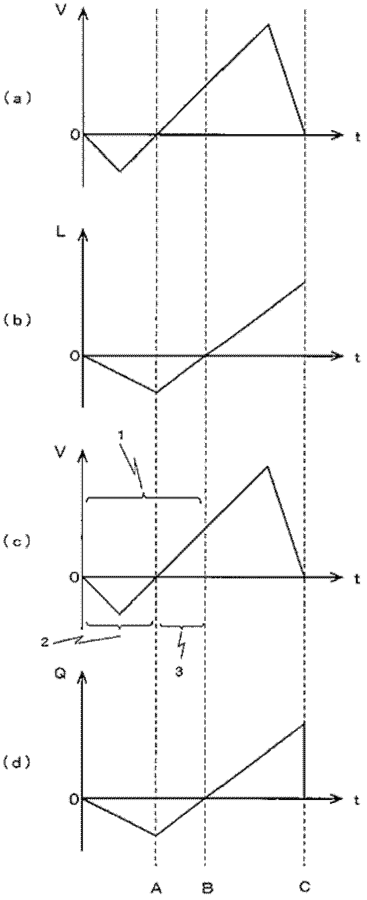
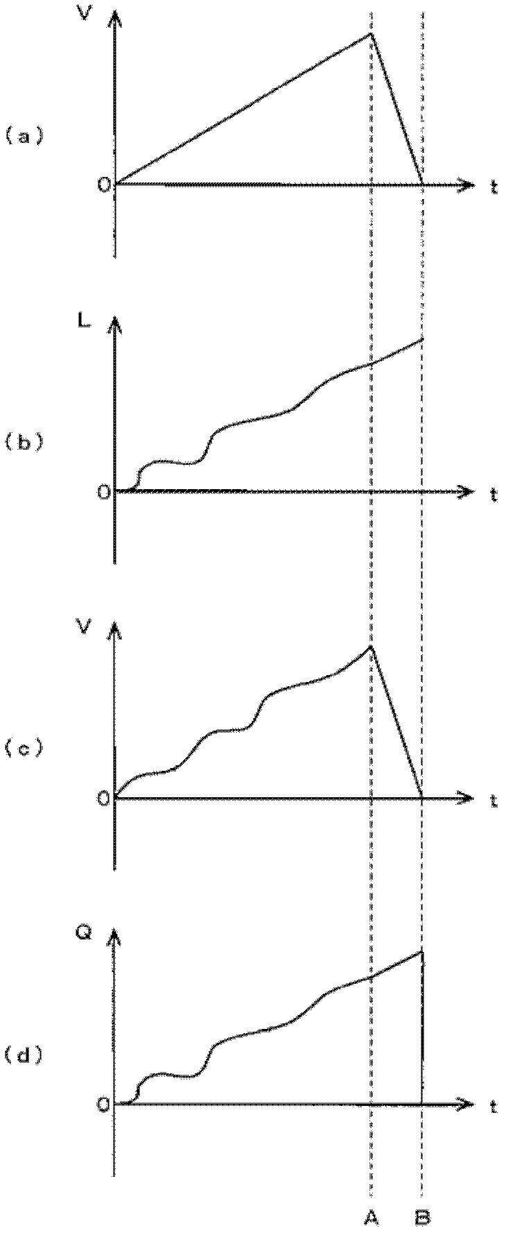
[0094] In the second embodiment, a method of discharging by combining different types of preparatory operations in the same discharge device as in the first embodiment will be described. Figures 5 to 9 Indicates the change in plunger speed with time.

[0095] (1) The method of performing preparatory action each time during continuous discharge [ Figure 5 ]

[0096]When the liquid material in the metering part is continuously discharged after filling the metering part once, and the liquid material in the metering part is discharged multiple times, when the discharge interval becomes longer or the discharge accuracy is important, such as Figure 5 As shown, preparatory action 1 is performed at the beginning of each discharge action. In this way, the accuracy of each ejection can be improved, and the variation between each ejection can be reduced.

[0097] (2) Method of setting small reciprocating motion as preparatory motion [ Image 6 ]

[0098] The plunger 6 normally st...


PUM


Abstract

Provided are a method, apparatus, and program for jetting a liquid material, which make it possible to stabilize the droplet shape and the jetting state of the liquid material to be jetted and make it possible to improve jetting accuracy. In the liquid material jetting method, a measuring section which measures the liquid material, a jetting port connected to one end of the measuring section, and a plunger which moves by sliding on the inner wall of the measuring section are provided, a filling step, wherein the measuring section is filled with the liquid material by moving the plunger in the direction opposite to the jetting port, and a jetting step, wherein the plunger is moved toward the jetting port and stopped and the liquid material is flown and jetted from the jetting port, are performed. The method is characterized in that the speed of the plunger in the jetting step is controlled to be constant by providing a preliminary operation step wherein the plunger is moved without jetting the liquid material.

Description

technical field [0001] The present invention relates to a discharge method, device and program for a liquid material. The discharge method moves a plunger sliding in a metering portion communicating with a nozzle provided with a discharge port by a desired amount to discharge the liquid material. By controlling the above-mentioned The action of the plunger does not cause fluctuations in the discharge amount of the liquid material, and a certain amount of liquid material can be repeatedly discharged. [0002] In addition, in this specification, "flying" means that the liquid material leaves from the discharge port before it comes into contact with the object to be coated. Background technique [0003] There are now expelling devices known as plunger pumps (or syringe pumps). This type of discharge device is often used when it is necessary to accurately discharge a certain amount of liquid material, such as in an ODF process during liquid crystal panel manufacture. [0004] ...

Claims


Application Information

Patent Timeline
Patent Type & Authority Applications(China)
IPC IPC(8): B05D1/26B05C5/00B05C11/10B05D3/00
CPCB41J2/16526B05B1/02G02F1/1303
Inventor 生岛和正
Owner MUSASHI ENG INC
Learn More