
Substrate processing apparatus and substrate processing method

A substrate processing device and substrate technology, which are applied in the fields of electrical components, semiconductor/solid-state device manufacturing, circuits, etc., can solve the problems of hindering the discharge of the treatment liquid, hinder the flow of the treatment liquid, etc., and achieve the effect of improving uniformity and stable discharge state.

Active Publication Date: 2018-12-21
DAINIPPON SCREEN MTG CO LTD
View PDF9 Cites 0 Cited by
  • Summary
  • Abstract
  • Description
  • Claims
  • Application Information

AI Technical Summary

Problems solved by technology

However, in the apparatus of Patent Document 2, when the processing liquid is discharged to the outside from the peripheral portion of the substrate, since the ring surrounding the substrate blocks the flow of the processing liquid, the discharge of the processing liquid is hindered.

Method used


Image

  • Substrate processing apparatus and substrate processing method
  • Substrate processing apparatus and substrate processing method
  • Substrate processing apparatus and substrate processing method

Examples


Embodiment approach

[0058]

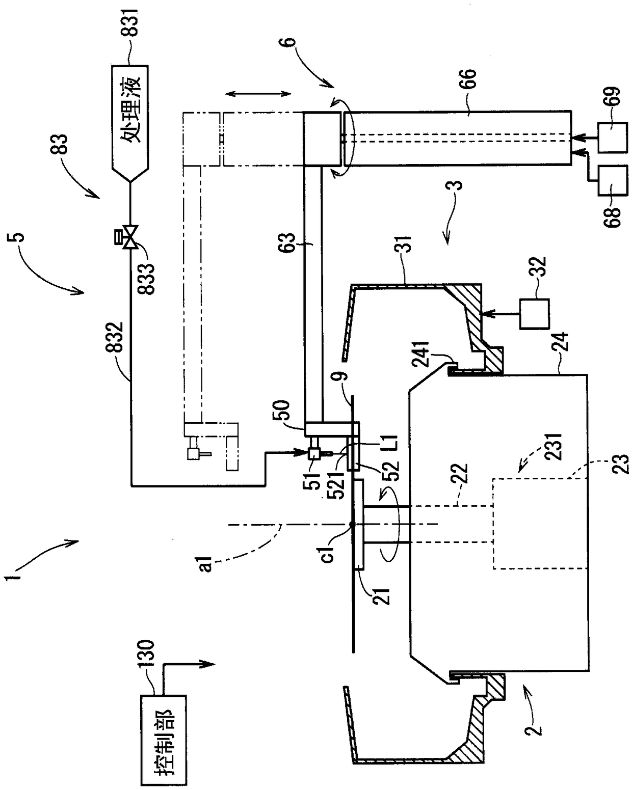
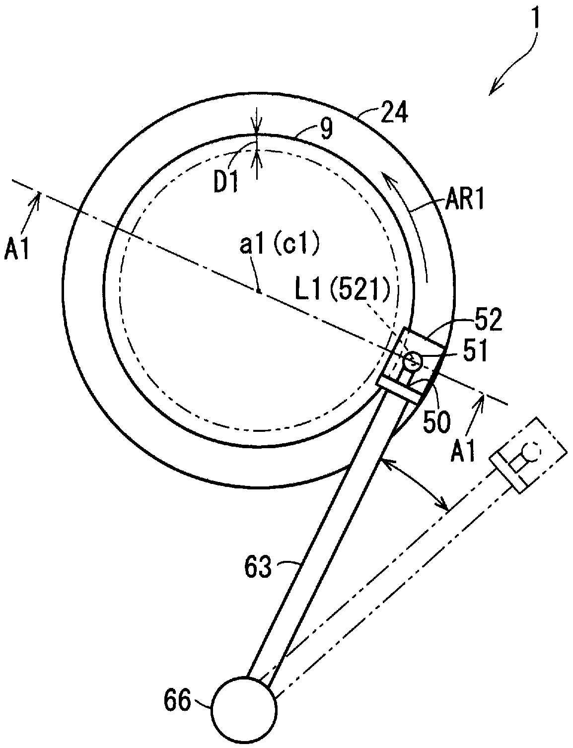
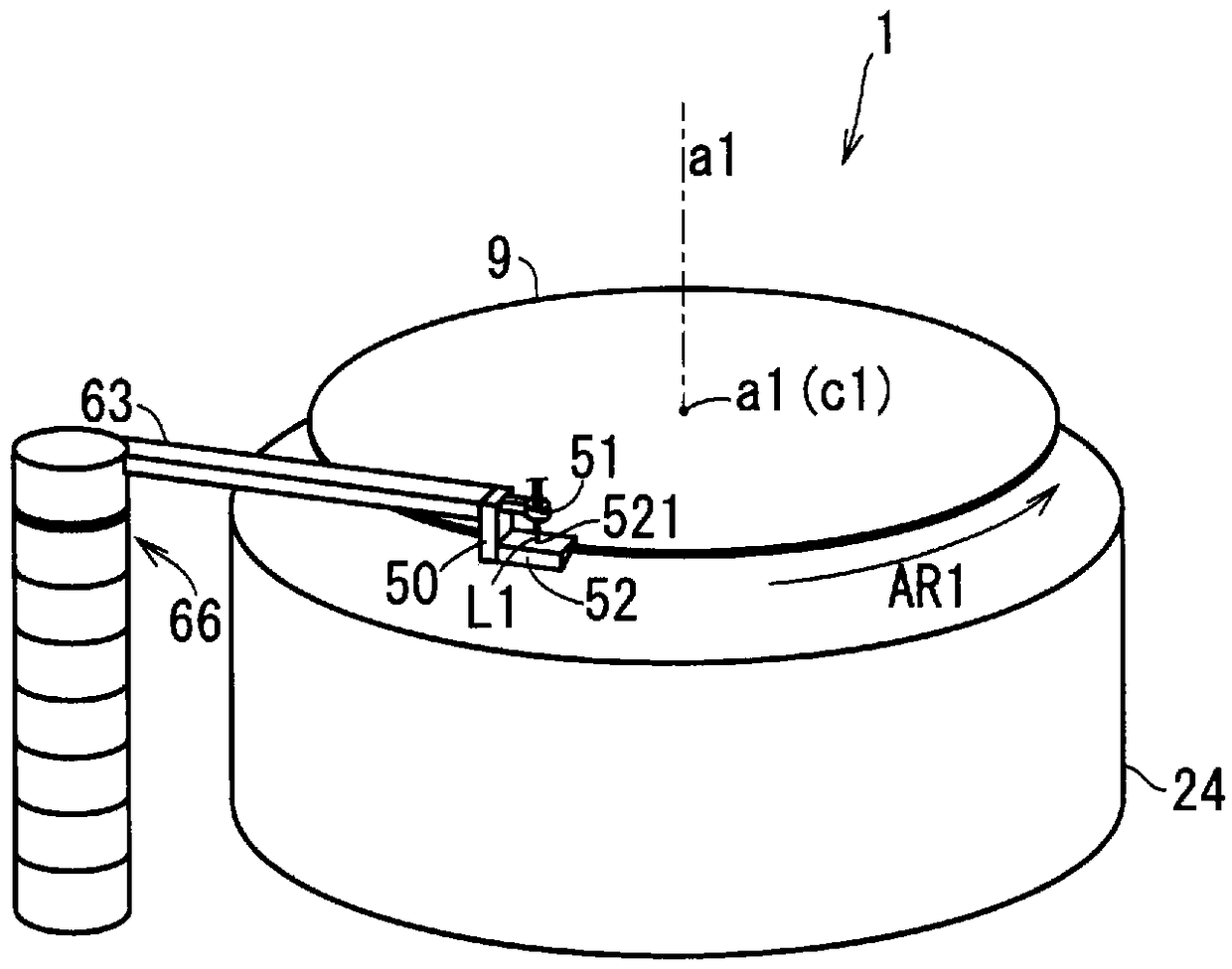
[0059] refer to Figure 1 ~ Figure 3 The configuration of the substrate processing apparatus 1 will be described. Figure 1 ~ Figure 3 It is a diagram for explaining the structure of the substrate processing apparatus 1 according to the embodiment. figure 1 , figure 2 It is a schematic side view and a schematic top view of the substrate processing apparatus 1 . image 3 It is a schematic perspective view of the substrate processing apparatus 1 viewed obliquely from above.

[0060] exist Figure 1 ~ Figure 3 In the figure, the substrate 9 is rotated in a predetermined rotation direction (direction of arrow AR1) around the rotation axis a1 by the spin chuck 21 in the state where the nozzle 51 and other members 52 are arranged at the respective processing positions. state. In addition, in figure 2 In the figure, the nozzle 51, other members 52, and the like arranged at the retracted position are shown by dotted lines. exist figure 2 , image 3 In , the desc...


PUM


Abstract

The purpose of the present invention is to narrow the processing width of a peripheral portion of a substrate, and to improve the uniformity of the processing width. In order to achieve the purpose, asubstrate processing apparatus according to the present invention comprises: a holding member which holds a substrate substantially horizontally from below and which is provided so as to be rotatablearound a predetermined rotation axis; a rotary member capable of rotating the holding member around the rotation axis; a separate member disposed on the outer side of the substrate along a radial direction of the substrate with a gap from an end face of the substrate being held by the holding member; and a nozzle that ejects a processing liquid from above an ejection target area included in an upper surface of the separate member so that at least a part of the processing liquid hits the ejection target area. The gap between the separate member and the end face of the substrate is set such that the processing liquid that has hit the ejection target area flows on an upper surface of the separate member, is ejected from an inner end on the rotation axis side of the upper surface, and hits anupper surface peripheral portion of the substrate from above.

Description

technical field [0001] The present invention relates to semiconductor wafers, glass substrates for liquid crystal display devices, glass substrates for plasma displays, substrates for optical disks, substrates for magnetic disks, substrates for magneto-optical disks, glass substrates for photomasks, substrates for solar cells, etc. (hereinafter referred to as A substrate processing apparatus for processing a "substrate"). Background technique [0002] As such a substrate processing apparatus, Patent Document 1 discloses a holding member that holds the substrate horizontally and a ring that surrounds the entire circumference of the substrate at a distance from the end surface of the substrate along the peripheral portion of the substrate while rotating together, A device that ejects the processing liquid so as to land on the center of the upper surface of the substrate. The ring surface is hydrophilic. In the case where the surface of the substrate is hydrophobic, if the ri...

Claims


Application Information

Patent Timeline
Patent Type & Authority Applications(China)
IPC IPC(8): H01L21/304
CPCH01L21/304H01L21/02052H01L21/02057H01L21/67051H01L21/6715H01L21/67259H01L21/67276H01L21/68764
Inventor 石井弘晃武明励
Owner DAINIPPON SCREEN MTG CO LTD
Learn More