Supercharge Your Innovation With Domain-Expert AI Agents!

Inkjet printhead assembly having backside electrical connection

An inkjet print head, print head technology, applied in printing, inking device, etc., can solve the problems of printing maintenance and harmful printing quality, etc.

Active Publication Date: 2012-05-23
MEMJET TECH LTD
View PDF11 Cites 12 Cited by
  • Summary
  • Abstract
  • Description
  • Claims
  • Application Information

AI Technical Summary

Problems solved by technology

However, wire bonds protrude from the ink-ejecting face of the printhead and thus can have detrimental effects on print maintenance and print quality

Method used


Image

  • Inkjet printhead assembly having backside electrical connection
  • Inkjet printhead assembly having backside electrical connection
  • Inkjet printhead assembly having backside electrical connection

Examples


Embodiment Construction

[0109] Supply ink to the printhead integrated circuit (IC)

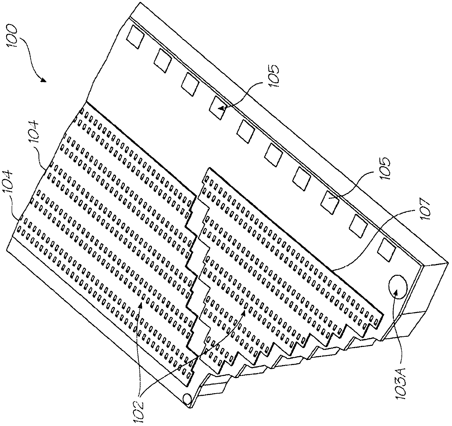
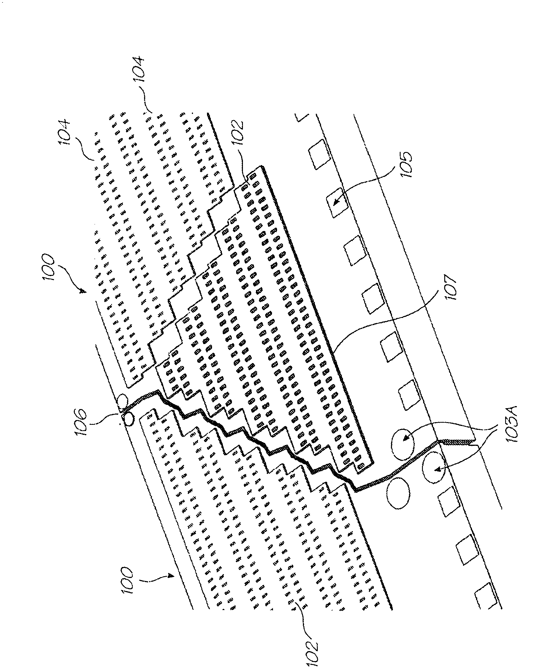
[0110] Applicants have thus far described printhead integrated circuits (or "chips") 100 that can be joined together in an end-to-end adjoining arrangement to define a pagewidth printhead. figure 1 The front side of a part of the printhead IC 100 is shown in a perspective view, while figure 2 A pair of printhead ICs are shown adjoining each other.

[0111] Each printhead IC 100 includes thousands of nozzles 102 arranged in a row. Such as figure 1 and 2 As shown in , the printhead IC 100 is configured to receive and print five different colors of ink (eg, CMYK and IR (infrared); CCMMY; or CMYKK). Each color channel 104 of printhead IC 100 includes pairs of nozzle rows, one row of the pair printing even dots and the other row of the pair printing odd dots. Nozzles from each color channel 104 are vertically aligned in the paper feed direction to perform high resolution (eg, 1600 dpi) dot-to-dot printing. The hori...


PUM


Abstract

An inkjet printhead assembly comprising an ink supply manifold: printhead integrated circuits and a connector film for supplying power to drive circuits in the printhead integrated circuits. Each prithead integrated circuit has a frontside comprising the drive e circuitry and inkjet nozzle assemblies, a backside attached to the ink supply manifold, and ink supply channels providing fluid communication between the backside and the inkjet nozzle assemblies. A connection end of the connector film is sandwiched between part of the ink supply manifold and the printhead integrated circuits.

Description

technical field [0001] The present invention relates to printers and especially inkjet printers. The present invention was primarily developed to provide improved printhead integrated circuit mounting to facilitate printhead maintenance. Background technique [0002] Applicants have previously demonstrated that pagewide inkjet printheads can be constructed using multiple printhead integrated circuits ("chips") contiguous end-to-end along the page width . Although this printhead integrated circuit arrangement has many advantages (such as minimizing the width of the printing area in the direction of paper feed), each printhead integrated circuit must still be connected to other printer electronics, and the other printer electronics must communicate with each other. A printhead integrated circuit supplies power and data. [0003] Applicants have so far described how to connect the printhead integrated circuits to an external power / data supply by wire bonding bond pads on eac...

Claims


Application Information

Patent Timeline
Patent Type & Authority Applications(China)
IPC IPC(8): B41J2/135
CPCB41J2/1626B41J2/155B41J2/1632B41J2/1648B41J2/14427B41J2/1635B41J2/1645B41J2/1639B41J2/14B41J2202/18B41J2/14016B41J2002/14491B41J2/1642B41J2/1631B41J2/135B41J2/175
Inventor G·J·麦克沃依R·P·S·欧瑞丽D·M·约翰斯通K·西尔弗布鲁克
Owner MEMJET TECH LTD
Features
  • R&D
  • Intellectual Property
  • Life Sciences
  • Materials
  • Tech Scout
  • Unparalleled Data Quality
  • Higher Quality Content
  • 60% Fewer Hallucinations
Learn More