
Device for checking a turbomachine engine

A technology of engines and turbines, applied in measuring devices, using sound waves/ultrasonic waves/infrasonic waves to analyze solids, using sound waves/ultrasonic waves/infrasonic waves for material analysis, etc., can solve problems such as difficulties and inaccessibility of non-destructive testing devices

Active Publication Date: 2012-05-23
SN DETUDE & DE CONSTR DE MOTEURS DAVIATION S N E C M A
View PDF6 Cites 2 Cited by
  • Summary
  • Abstract
  • Description
  • Claims
  • Application Information

AI Technical Summary

Problems solved by technology

[0006] As a result, certain areas of the turbine engine remain inaccessible to known non-destructive inspection devices as they are not designed to pass through small sized ports or passages and through multiple successive misalignments mouth and / or access
[0007] Also, when inspecting a part, the probe typically needs to remain stationary relative to the engine, which is difficult with the aforementioned prior art rods

Method used


Image

  • Device for checking a turbomachine engine
  • Device for checking a turbomachine engine
  • Device for checking a turbomachine engine

Examples


Embodiment Construction

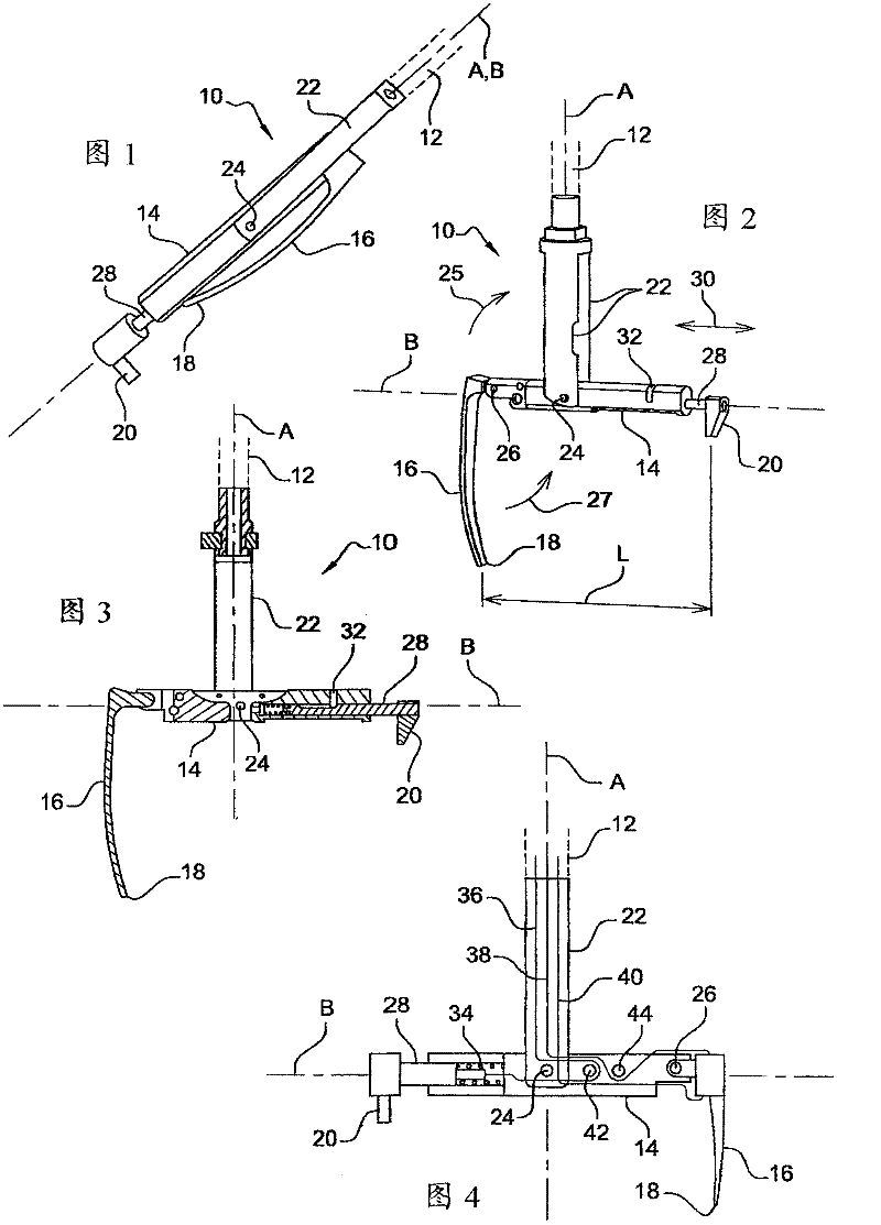
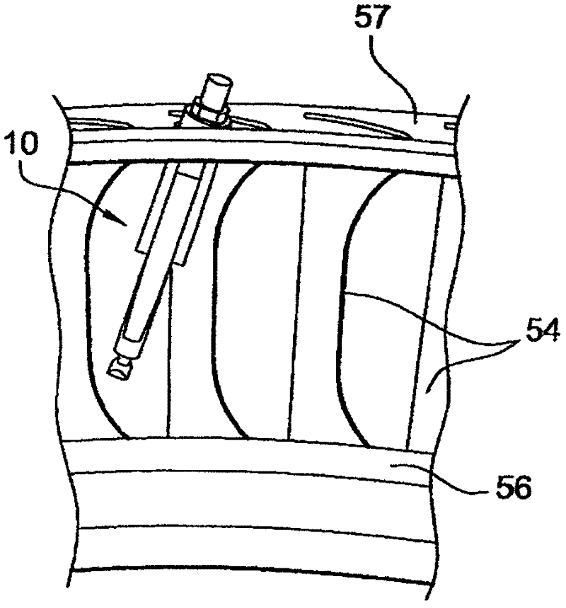
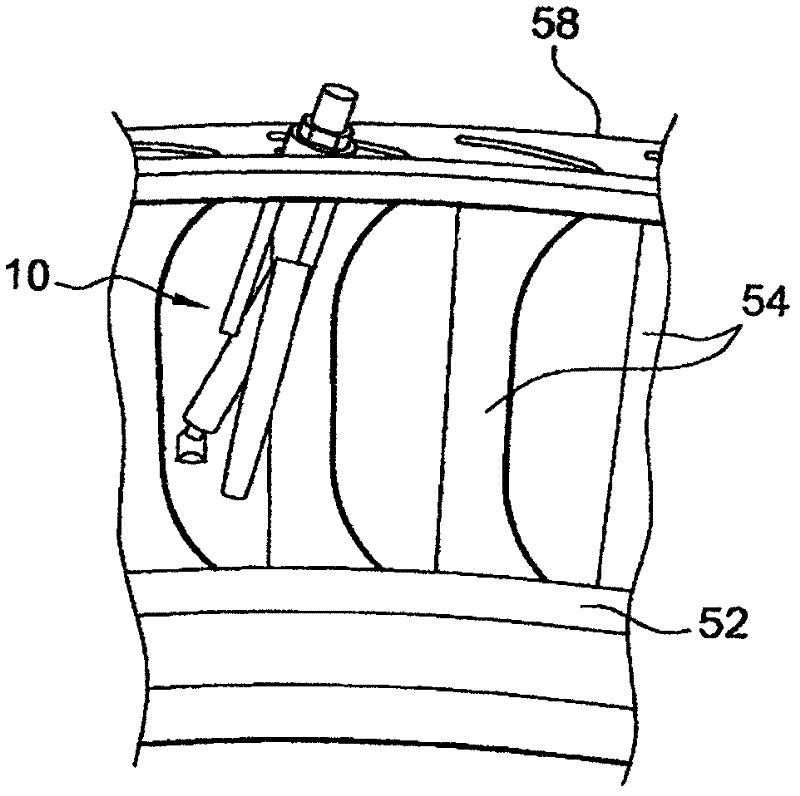
[0026] see first Figures 1 to 4 , which shows an apparatus 10 of the present invention for non-destructive inspection of turbine engine components hereinafter referred to Figures 5 to 8 is partially described.

[0027] Apparatus 10 includes a longitudinal rod 12 (shown in phantom) having a finger 14 pivotally mounted at its distal end, which carries at one end a blade 16 for supporting an inspection probe 18, and at its The opposite end carries a slider 20 for bearing against and / or gripping on an element of the engine.

[0028] The rod 12 carries at its distal end two parallel spaced apart longitudinal lugs 22 , the fingers 14 being pivotally mounted by means of their intermediate portions on pins 24 extending between the free ends of the lugs 22 .

[0029] Finger 14 can be used as figure 1 The folded position shown in where it extends between the lugs parallel to the longitudinal axis A of the rod is the same as Figures 2 to 4 Pivotal movement (arrow 25 ) between the ...


PUM

PropertyMeasurementUnit
diameteraaaaaaaaaa

Abstract

A device (10) for the in situ non-destructive testing of parts of a turbomachine engine, comprising a stem (12) supporting, at its far end, a pivoting finger (14) which has, at one of its ends, a blade (16) for supporting a test probe (18) and, at its opposite end, a shoe (20) for bearing on and / or attachment to a component of the engine, this shoe being able to move in a direction (30) parallel to the longitudinal axis of the finger.

Description

technical field [0001] The invention relates to a device for in-situ non-destructive inspection of components of engines, in particular turbine engines. Background technique [0002] Non-destructive inspection (NDI) of turbine engine components is used to verify the condition of said components without causing damage. Under certain circumstances, such inspections may require the engine to be removed and partially disassembled to inspect components that are difficult to access by the inspection device. [0003] Known inspection devices consist of a rigid rod carrying an inspection probe or sensor at its distal end. When the turbine engine is equipped with sight ports, the rod is inserted into the turbine engine through one of these ports to perform an in-situ inspection of the turbine engine components, eliminating the need to remove or disassemble the engine. [0004] However, the area accessible by the rod is very limited and is usually positioned in alignment with and a ...

Claims


Application Information

Patent Timeline
Patent Type & Authority Applications(China)
IPC IPC(8): G01N27/90G01N29/22G01N29/24
CPCG01N29/24G01N27/9033G01N2291/2693G01N29/223G01N29/07G01N27/9006
Inventor 帕特里克·盖斯侬昆廷·米斯特拉尔西尔维·莫泽尔尼古拉斯·萨马克
Owner SN DETUDE & DE CONSTR DE MOTEURS DAVIATION S N E C M A
Learn More