

DC/DC power converter
A power conversion device and voltage technology, applied in the direction of output power conversion device, electrical components, regulating electrical variables, etc. problem, to achieve the effect of reducing power consumption
- Summary
- Abstract
- Description
- Claims
- Application Information
AI Technical Summary
Problems solved by technology
Method used
Image

Examples
Embodiment approach 1
[0028] Hereinafter, the DC / DC power conversion device according to Embodiment 1 of the present invention will be described.
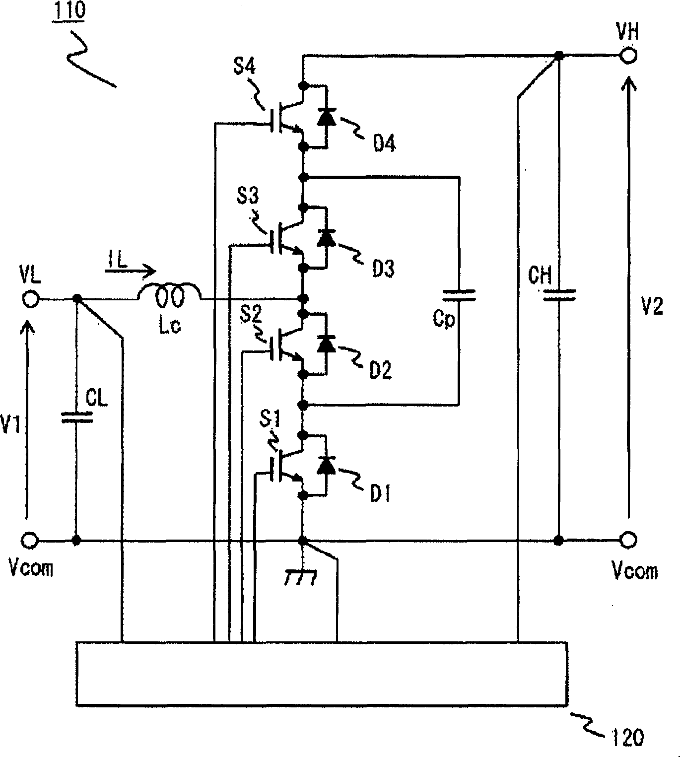
[0029] figure 1 The circuit configuration of the DC / DC power conversion device according to Embodiment 1 of the present invention is shown. Such as figure 1 As shown, the DC / DC power conversion device has the following DC / DC power conversion function: convert the voltage V1 input between the low-voltage voltage terminals VL and Vcom into a voltage V2 boosted above V1 and output it to the high-voltage voltage terminals VH and Vcom Between Vcom (boost operation), or convert the voltage V2 input between the high-voltage voltage terminal VH and Vcom into a voltage V1 that is stepped down below V2 and output it between the low-voltage voltage terminal VL and Vcom (step-down operation) .
[0030] The DC / DC power conversion device includes a main circuit 110 and a control circuit 120 . The main circuit 110 includes: smoothing capacitors CL, CH to smooth th...
Embodiment approach 2
[0138] Hereinafter, a DC / DC power converter according to Embodiment 2 of the present invention will be described. Part of the circuit configuration is different from the DC / DC power conversion device of Embodiment 1 above, but the control operation related to the buck-boost is basically the same.
[0139] Figure 7 A circuit configuration of a DC / DC power conversion device according to Embodiment 2 of the present invention is shown. Such as Figure 7 As shown, the DC / DC power conversion device has the following DC / DC power conversion function: the voltage V1 input between the low-voltage voltage terminals VL and VcomL is converted into a voltage V2 boosted above V1 and output to the high-voltage voltage terminals VH and VcomL Between VcomH (boost operation), or convert the voltage V2 input between the high-voltage voltage terminals VH and VcomH to a voltage V1 that is lowered to V2 or less, and output it between the low-voltage voltage terminals VL and VcomL (step-down opera...
Embodiment approach 3
[0205] In Embodiment 1, as described above, it is necessary to continuously change the switching frequency f according to Equation (14) and Equation (15) so that the magnitude of the current ripple becomes constant, and there is a problem that the control becomes complicated. In addition, at the voltage ratio k=2, the effective switching frequency f cannot be obtained from the two equations, so this is also as described. When it is desired to operate near the voltage ratio k=2, the switching frequency f needs to be Special consideration for control such as setting to an extremely small value.
[0206] Embodiment 3 of the present invention was completed in consideration of the above points. Instead of making the switching frequency f variable in accordance with the voltage ratio k, the switching frequency f is changed in several fixed types, and the reactor's When the inductance value L is set so large (without making the size of the reactor so large), the current ripple can be...
PUM
 Abstract
Description
Claims
Application Information