Reverse type self-luminous reflecting mirror

A self-luminous, mirror technology, applied in the direction of reflector, light source, refractor, etc., can solve the problems of affecting the imaging quality, image comparison misjudgment, etc., to improve the imaging quality and avoid the effect of directly illuminating the camera lens

Inactive Publication Date: 2012-05-30
KUSN MINGJIU ELECTROMECHANICAL
View PDF0 Cites 0 Cited by
  • Summary
  • Abstract
  • Description
  • Claims
  • Application Information

AI Technical Summary

Problems solved by technology

[0004] Although the existing technology can obtain multiple angle images of the object 1 to be measured at the same time, since the light source 3 and the reflector 31 are not at the same angle, shadows will be formed on the object 1 to be measured, resulting in misjudgment of the image comparison ; and because the light source 3 directly shoots into the lens of the camera 2, it is easy to form a halo and affect the image quality

Method used


Image

  • Reverse type self-luminous reflecting mirror
  • Reverse type self-luminous reflecting mirror
  • Reverse type self-luminous reflecting mirror

Examples


Embodiment Construction

[0014] The description of the following embodiments refers to the attached drawings to illustrate specific embodiments in which the present invention can be implemented. The directional terms mentioned in the present invention, such as "up", "down", "front", "rear", "left", "right", "top", "bottom", etc., are only for reference to additional drawings direction. Therefore, the directional terms used are used to describe and understand the present invention, rather than to limit the present invention.

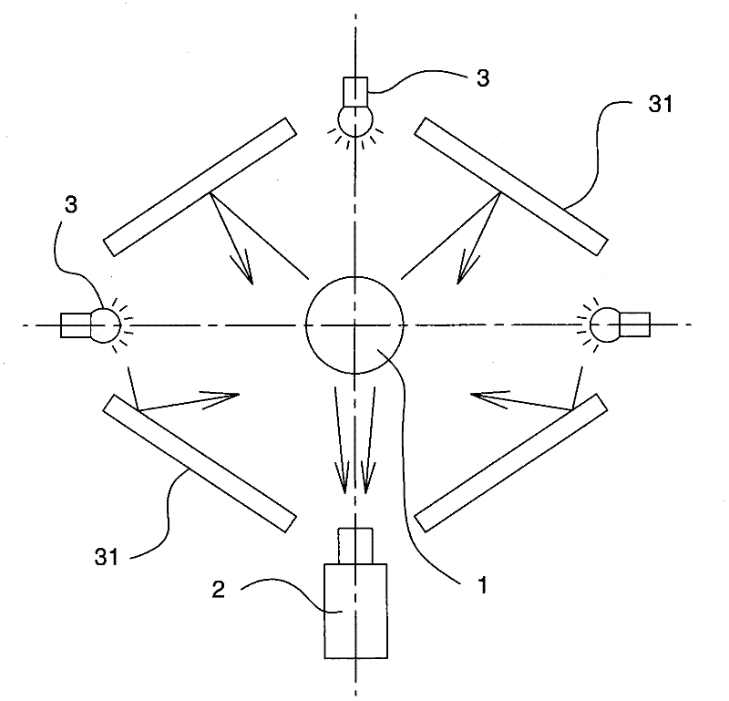
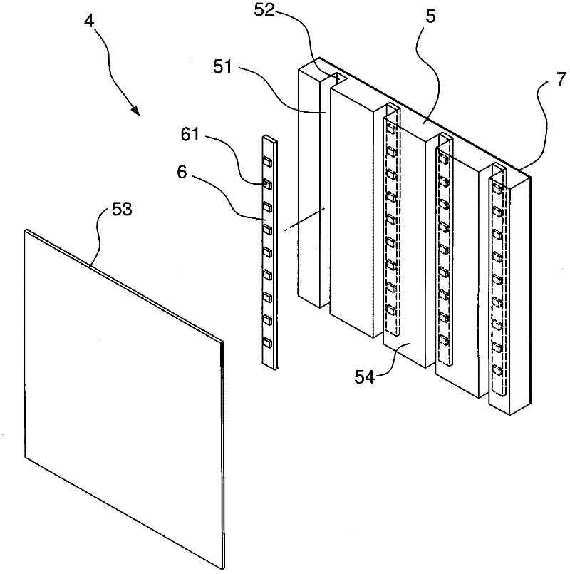
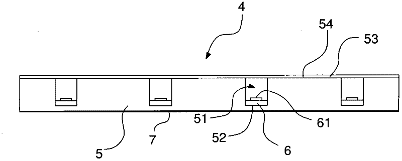
[0015] Please refer to Figure 2 to Figure 4 The reverse self-luminous reflector of the present invention shown, wherein figure 2 It is a three-dimensional exploded view of the reverse self-luminous mirror of the present invention; image 3 It is the combined side view of the reverse self-luminous reflector of the present invention; Figure 4 It is a partial cross-sectional view of the combined reverse self-luminous mirror of the present invention; Figure 5 It is a schematic diag...


PUM


Abstract

The invention discloses a reverse type self-luminous reflecting mirror, which comprises an acryl plate, a plurality of circuit boards and a light reflecting sheet, wherein the acryl plate is a plate sheet capable of scattering light rays; a plurality of containing grooves are formed on one surface of the acryl plate; the bottom of each containing groove is provided with a base; the circuit boards are laid in the bases of the containing grooves; a plurality of light emitting components are arranged on the surfaces of the circuit boards; the light reflecting sheet is covered on the surface of the acryl plate, which is provided with containing groove openings, and reflects light rays of the light emitting components; and the surface of the other surface of the acryl plate is provided with a semi-light-reflecting coating. By adopting the reverse type self-luminous reflecting mirror disclosed by the invention, an even lighting source can be provided and images also can be reflected.

Description

【Technical Field】 [0001] The present invention relates to a self-luminous reflector, in particular to a reverse self-luminous reflector that uses an acrylic plate and a reflector to reflect a light source, so that the reflector can reflect images and provide the light source at the same time. 【Background technique】 [0002] With the miniaturization of products, the size of various parts is gradually reduced, and the inspection procedures and inspection equipment in the production process are also adjusted to the miniature size. Nowadays, the analytical capabilities of digital images have been greatly improved, and digital images taken with optical lenses combined with automatic computer inspection equipment have gradually become popular. Many inspections performed manually in the past have also been replaced by automatic optical inspection equipment. [0003] Please refer to figure 1 As shown, it is a schematic diagram of the configuration of an automatic optical inspection device ...

Claims


Application Information

Patent Timeline
Patent Type & Authority Applications(China)
IPC IPC(8): F21V5/00F21V7/22F21V29/00F21Y101/02F21V29/503
Inventor 张旻郁
Owner KUSN MINGJIU ELECTROMECHANICAL
Why Eureka
Try Eureka