
Blood rheometer pipeline system

A technology of pipeline system and blood flow, applied in the direction of instruments, analytical materials, etc., to achieve the effect of improving the accuracy and reliability of measurement

Inactive Publication Date: 2012-05-30
SHANGHAI ANCAI INTELLIGENT TECH
View PDF0 Cites 4 Cited by
  • Summary
  • Abstract
  • Description
  • Claims
  • Application Information

AI Technical Summary

Problems solved by technology

However, there has never been a blood flow meter pipeline system in which the sensor is applied in the prior art

Method used


Image

  • Blood rheometer pipeline system
  • Blood rheometer pipeline system

Examples


Embodiment Construction

[0009] The present invention will be described in further detail below in conjunction with the accompanying drawings and specific implementation methods.

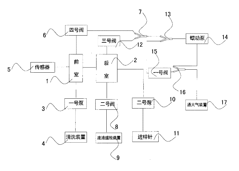
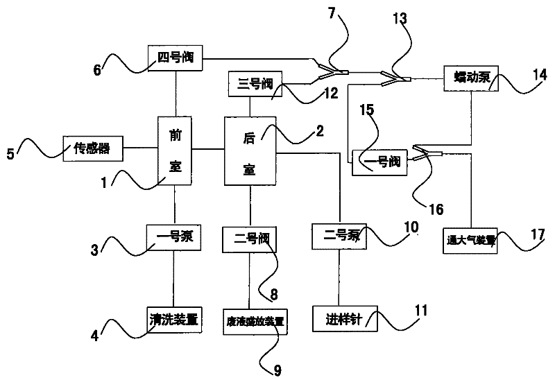
[0010] Such as figure 1 As shown, the blood flow meter pipeline system of the present invention includes an anterior chamber 1 and a rear chamber 2, the end one of the anterior chamber 1 is connected with the end one of the back chamber 2, and the end two of the anterior chamber 1 is connected with the first pump 3 The cleaning device 4 is connected, the terminal 3 of the front chamber 1 is connected with the sensor 5, the terminal 4 of the anterior chamber is connected with the No. 1 microtube 7 through the No. Connect with release device 9, end three of back chamber 2 is connected with sampling needle 11 through No. 2 pump 10, end four of back chamber is connected with No. 1 microtube 7 through No. 3 valve 12; No. 1 microtube 7 is also connected with No. No. microcapillary tube 13 is connected, No. 2 microcapillary tube ...


PUM


Abstract

The invention discloses a blood rheometer pipeline system which comprises a front chamber and a back chamber; an end one of the front chamber is connected with an end one of the back chamber; an end two of the front chamber is connected with a cleaning device through a No.1 pump; an end three of the front chamber is connected with a sensor; an end four of the front chamber is connected with a No.1 micropipe through a No.4 valve; an end two of the back chamber is connected with a waste liquid accommodating device through a No.2 valve; an end three of the back chamber is connected with a sampling needle through a No.2 pump; an end four of the back chamber is connected with the No.1 micropipe through a No.3 valve; the No.1 micropipe is also connected with a No.2 micropipe; the No.2 micropipe is connected with a peristaltic pump, and is also connected with a No.3 micropipe through the No.4 valve; the No.3 micropipe is also connected with an atmosphere-communicating device. The blood rheometer pipeline system of the invention successfully adopts a sensor in the whole pipeline system, and thus the measurement accuracy and reliability of the whole blood rheometer are improved.

Description

technical field [0001] The invention relates to a pipeline system, in particular to a blood flow meter pipeline system. Background technique [0002] Blood flow meter, namely blood rheometer, is an important tool for measuring whole blood viscosity and plasma viscosity, and has an important application in clinical blood rheology. Sensor-type blood flow meter is generally composed of three parts: measurement system, computer system and automatic sampling system, and the measurement system is composed of pipeline system and signal conversion circuit. With the support of the rapid development of computer technology, the Whole blood or plasma flows through the detector under a continuously varying high to low shear force. The pipeline system is the core of the entire measurement system, and its function is to flow when the sample experiences a slow change in flow rate. However, there has not been a blood flow meter pipeline system in which the sensor is applied in the prior ar...

Claims


Application Information

Patent Timeline
IPC IPC(8): G01N15/04
Inventor 朱明焕
Owner SHANGHAI ANCAI INTELLIGENT TECH
Learn More