
Light receiving and outputting control equipment

A technology of output control and light reception, applied in optical recording heads, beam guides, recording/reproducing by optical methods, etc., can solve the problem of insufficient effect of wobble signal amplitude characteristics or tracking servo characteristics, etc.

Inactive Publication Date: 2012-05-30
DALIAN ZHAOYANG SOFTWARE TECH
View PDF2 Cites 0 Cited by
  • Summary
  • Abstract
  • Description
  • Claims
  • Application Information

AI Technical Summary

Problems solved by technology

[0014] Therefore, if the unequal light-receiving output of each of the four-divided light-receiving regions is corrected by the method of using the focus error signal, when the tracking control method used is the push-pull method or the differential push-pull method applied thereto, in Sufficient effects may not be obtained in terms of improving the amplitude characteristics of the wobble signal or the tracking servo characteristics

Method used


Image

  • Light receiving and outputting control equipment
  • Light receiving and outputting control equipment
  • Light receiving and outputting control equipment

Examples


Embodiment Construction

[0029] At least the following details are apparent from the description and drawings.

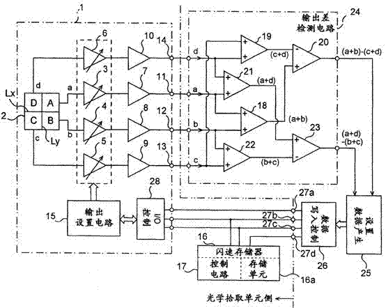
[0030] attached figure 1 is a circuit block diagram of one embodiment of the light receiving output control device of the photodetector in the optical pickup unit according to the present invention.

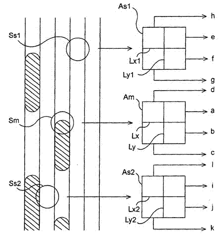
[0031] attached figure 2 It is an explanatory diagram describing the focus control mode and the tracking control mode. attached figure 2 Indicates the light-receiving area corresponding to the optical pickup unit that uses the phase difference method for DVD-ROM and the differential push-pull method for DVD±R / RW and CD in the tracking control mode, and in the focus control mode On the one hand, the astigmatism method is used for various recording / reproducing CDs, and the differential astigmatism method is used for various recording / reproducing DVDs, and an arrangement of spots of a laser beam emitted from an optical pickup unit to a magnetic disk is shown.

[0032] Although not shown bec...


PUM


Abstract

The invention discloses light receiving and outputting control equipment. In an optical pick-up device of a photoelectric detector which is configured to guide laser beams emitted from a laser source to an objective lens, converge the laser beams with the objective lens to irradiate onto a magnetic disk, and guide the laser beams reflected and returned by the magnetic disk to a light receiving area consisting of a plurality of sections, the photoelectric detector is provided with each amplifier which corresponds to each section of the light receiving area, each output terminal for outputting corresponding to each light receiving and outputting from each section of the photoelectric detector device through each amplifier, and an output setting circuit; the output setting circuit is used for setting each light receiving and outputting from each output terminal by changing the gain of each amplifier or attenuating the input or output of each amplifier with an attenuator; and the output setting circuit is used for calibrating each light receiving and outputting from each output terminal according to an output difference generated in each light receiving and outputting from each output terminal.

Description

technical field [0001] The present invention generally relates to a light-receiving output control device of a photodetector in an optical pickup unit configured to guide a laser beam reflected from a magnetic disk and returned to a photodetector including a light-receiving area composed of a plurality of segments. In particular, the present invention relates to a light-receiving output control device of a photodetector in an optical pickup unit, which takes measures for an output difference in each light-receiving output from the photodetector, wherein the output difference is projected on the photodetector The displacement of the light-receiving point on the light-receiving area of ​​the device is caused. Background technique [0002] The method of astigmatism and its applications are widely used in optical pickup units for optically recording and reproducing signals to optical discs, such as CD and DVD, using laser beams. That is, the differential astigmatism method. Fo...

Claims


Application Information

Patent Timeline
Patent Type & Authority Applications(China)
IPC IPC(8): G11B7/135G11B7/13
Inventor 栾晓健
Owner DALIAN ZHAOYANG SOFTWARE TECH
Learn More