Backflow preventer with built-in filter screen and no external piping

A backflow preventer and filter screen technology, which is applied in filtration and separation, valve devices, chemical instruments and methods, etc., can solve problems such as hidden dangers of water supply safety, easy loss, and long structure, so as to ensure water supply safety, save installation space, and reduce costs. The effect of head loss

Inactive Publication Date: 2012-06-06
TIANJIN GUOWEI FEEDING & DRAINAGE EQUIP MENT MFG
View PDF8 Cites 4 Cited by
  • Summary
  • Abstract
  • Description
  • Claims
  • Application Information

AI Technical Summary

Problems solved by technology

[0002] The current backflow preventer adopts a "Y" type straight-line structure, which is relatively long. Many renovation projects cannot be carried out as scheduled due to size problems. The through pipes are all external pipes
On the one hand, the head loss of this structure is generally 7-9 meters. Because there are important structural design problems that have not been broken through, the head loss cannot be reduced. If this structure is used under the existing water supply conditions, the head loss will be large. Too many users cannot drink tap water, which is an important reason why this type of product cannot be promoted. On the other hand, when the diaphragm is damaged, it is difficult to determine whether the backflow water enters the upstream through the bypass pipe, which is not conducive to the safety of water supply. The through pipe is a weak point, easy to be lost, destroyed, or poisoned by bad people. It is a fatal problem that this type of product has not solved so far. Governments of various countries are well aware of the importance of this type of product, but because of the fatal weakness of this type of product However, the water safety of residents cannot be guaranteed, and the water supply of the entire town brings major safety hazards.

Method used


Image

  • Backflow preventer with built-in filter screen and no external piping
  • Backflow preventer with built-in filter screen and no external piping
  • Backflow preventer with built-in filter screen and no external piping

Examples


Embodiment Construction

[0009] The structure of the backflow preventer of the present invention will be described with reference to the drawings and embodiments.

[0010] The built-in filter and the backflow preventer that does not require external piping are structures that have made major breakthroughs in the technical field.

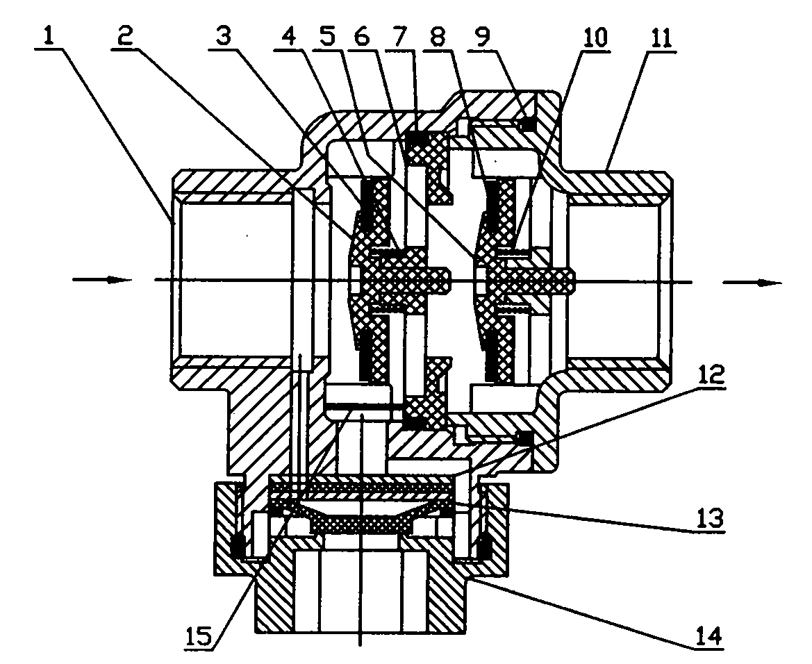
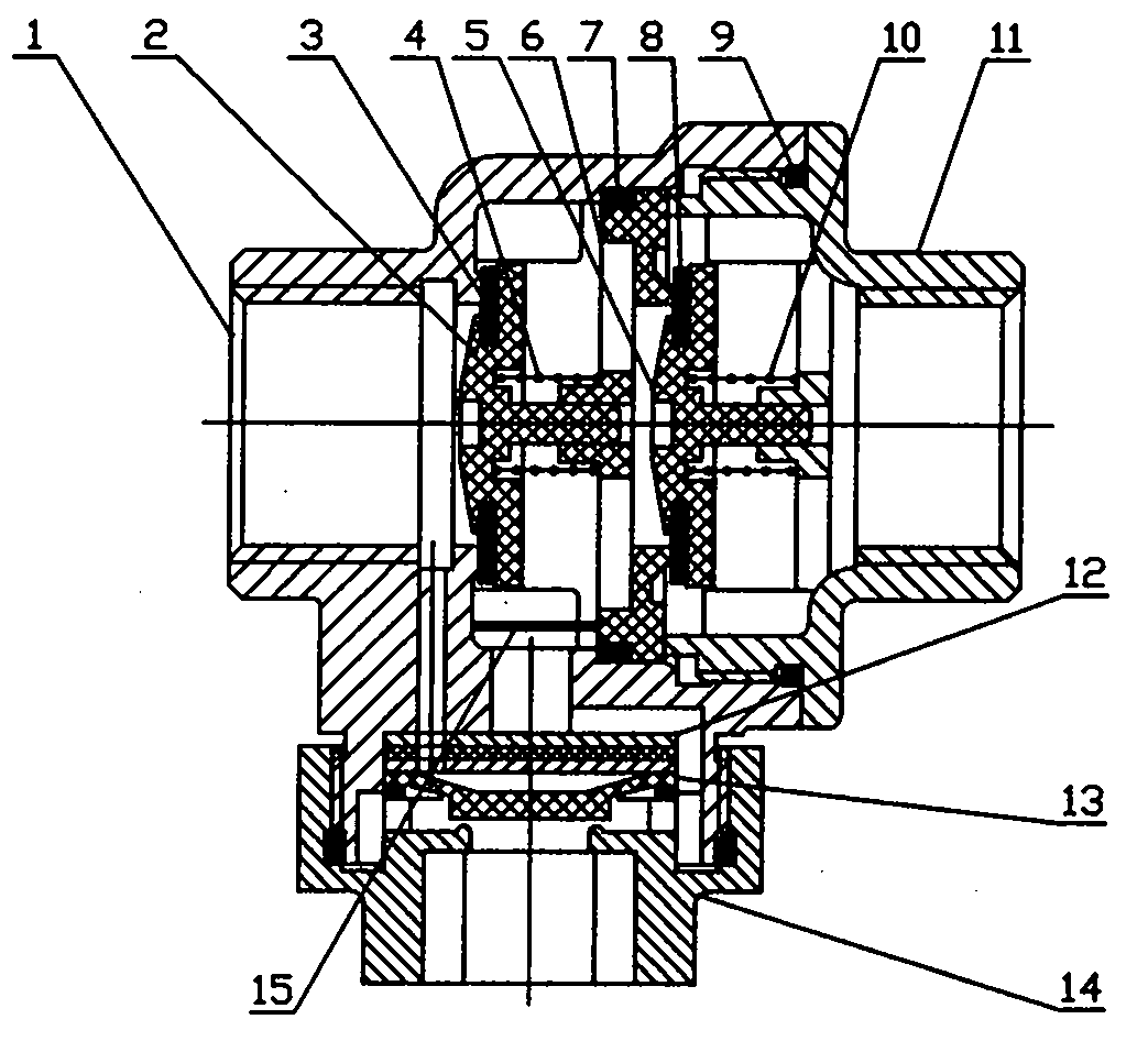
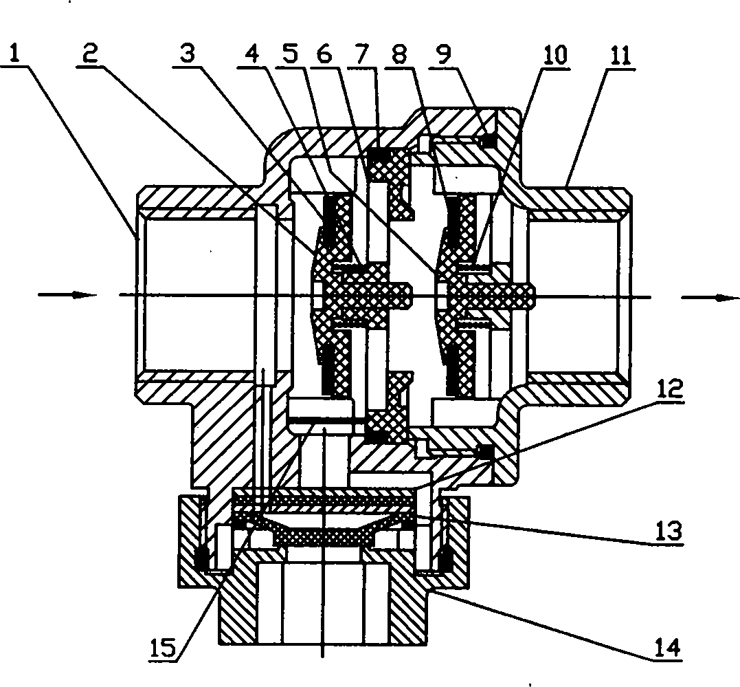
[0011] Such as figure 1 , 2 as shown, figure 1 The middle arrow indicates the direction of medium flow. A backflow preventer with a built-in filter and no external piping, the backflow preventer includes valve body one (1) and valve body two (11) connected and communicated through threads, the backflow preventer includes valve body one (1 ), valve plate one (2), sealing ring one (3), spring one (4), valve plate two (5), valve seat (6), sealing ring two (7), sealing ring three (8), seal Ring four (9), spring two (10), valve body two (11), diaphragm (12), gasket (13), lower cover (14), filter screen (15), the valve plate one (2 ) is arranged in the middle of the valve bod...


PUM


Abstract

The invention provides a backflow preventer with a built-in filter screen and no external piping. The backflow preventer comprises a valve body I and a valve body II which are in threaded connection and communication; when a valve is closed, a valve plate I leftwards linearly moves to be tightly attached to a sealing surface on the valve body I under the action of a spring I; and meanwhile, a valve plate II leftwards linearly moves to be tightly attached to a sealing surface on a valve seat under the action of a spring II. A diaphragm is arranged in a control chamber of a drain opening; the periphery of the diaphragm is laid on the top end surface of a sealing gasket, is covered by a lower cover and is fastened at the drain opening of the valve body to form the control chamber; and water of a water inlet enters the control chamber through a through hole in the valve body I to push the diaphragm to upwards or downwards move. The backflow preventer has the beneficial effects that: according to the backflow preventer with the structure, a pressure medium in a pipeline can be strictly limited and can only flow in one way; the structure is compact; a mounting space is saved; the requirements that a backflow medium in a pipeline or a medium positioned at the criticality backflow can be discharged out of the pipe at any work condition can be met; air isolation is formed; no plug-in accessories are required; the safety of water supply is ensured; and the pollution is prevented.

Description

technical field [0001] The invention relates to a valve structure, in particular to a backflow preventer with a built-in filter net and no external piping. Background technique [0002] The current backflow preventer adopts a "Y" type straight-line structure, which is relatively long. Many renovation projects cannot be carried out as scheduled due to size problems. The through pipes are all external pipes. On the one hand, the head loss of this structure is generally 7-9 meters. Because there are important structural design problems that have not been broken through, the head loss cannot be reduced. If this structure is used under the existing water supply conditions, the head loss will be large. Too many users cannot drink tap water, which is an important reason why this type of product cannot be promoted. On the other hand, when the diaphragm is damaged, it is difficult to determine whether the backflow water enters the upstream through the bypass pipe, which is not condu...

Claims


Application Information

Patent Timeline
Patent Type & Authority Applications(China)
IPC IPC(8): F16K15/00B01D35/04
Inventor 刘永刘庆龚高石
Owner TIANJIN GUOWEI FEEDING & DRAINAGE EQUIP MENT MFG
Why Eureka
Try Eureka