Eureka AIR delivers breakthrough ideas for toughest innovation challenges, trusted by R&D personnel around the world.

Automatic focusing module

A technology of auto-focusing and focusing, applied in installation, optics, instruments, etc., can solve the problems of friction and peeling, unstable conduction of metal conduction layer, etc., to achieve easy manufacturing process, avoid contact conduction, and reduce the number of module parts. Effect

Active Publication Date: 2012-06-06
LARGAN PRECISION
View PDF6 Cites 2 Cited by
  • Summary
  • Abstract
  • Description
  • Claims
  • Application Information

AI Technical Summary

Problems solved by technology

However, the above-mentioned existing autofocus module 10 has the following disadvantages: 1. the conduction of the metal conduction layer is unstable
3. The exposed metal conduction layer is easy to oxidize, and it is easy to contact with other parts or peel off by friction

Method used


Image

  • Automatic focusing module
  • Automatic focusing module
  • Automatic focusing module

Examples


Embodiment Construction

[0036] In order to make the object, technical solution and advantages of the present invention clearer, the embodiments of the present invention will be further described in detail below in conjunction with the accompanying drawings. Here, the exemplary embodiments and descriptions of the present invention are used to explain the present invention, but not to limit the present invention.

[0037] The autofocus module of the present invention will be described in detail through the following specific embodiments in conjunction with the accompanying drawings.

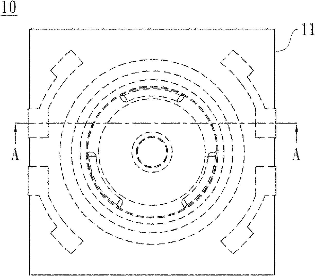
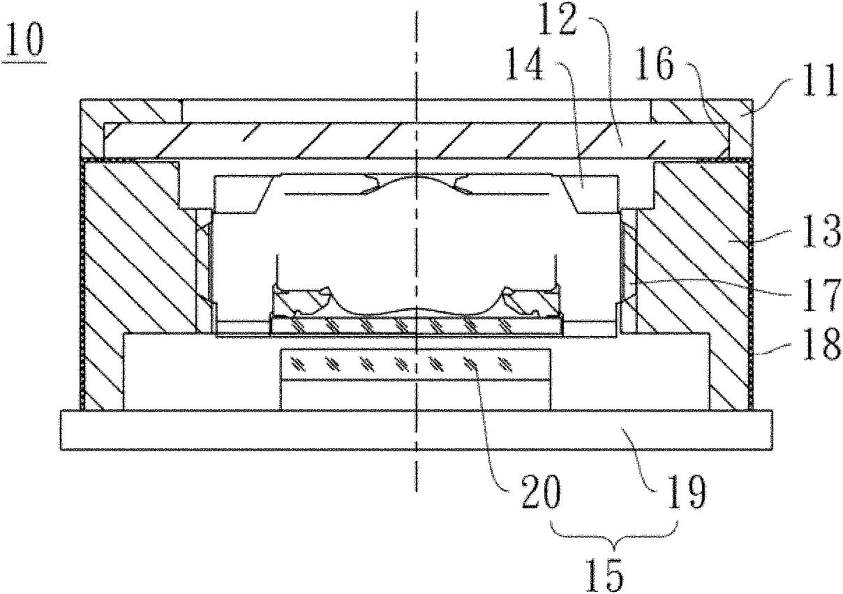
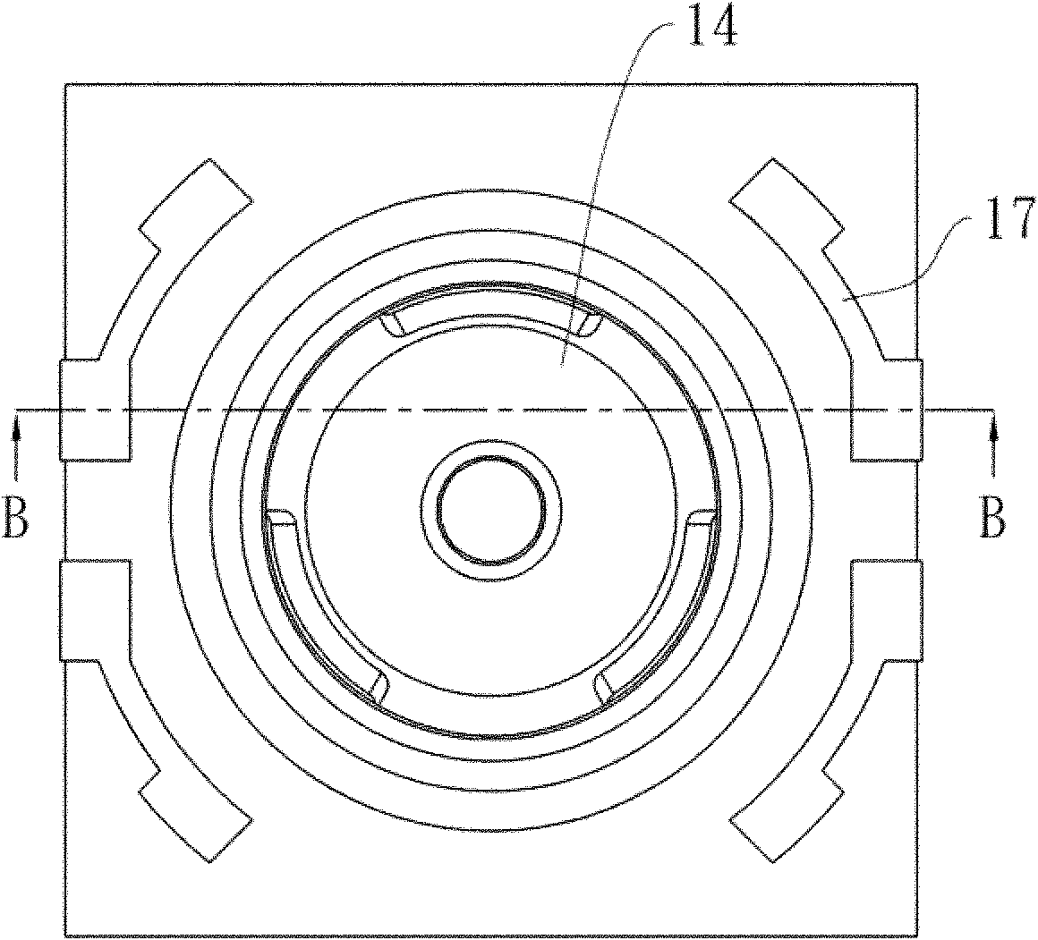
[0038] see Figure 3A and Figure 3B , respectively showing the top view schematic diagram and the first embodiment of the autofocus module of the present invention Figure 3A Schematic diagram of the section along line C-C. In this specific embodiment, the autofocus module 100 of the present invention at least includes a zoom holder 110, an electronically controlled zoom member 120, at least one power supply conductor...


PUM


Abstract

The invention discloses an automatic focusing module at least comprising an installation pedestal, an electronically controlled zooming member, and at least one power transmission member. The installation pedestal at least is accommodated with a lens as well as the electronically controlled zooming member is assembled at one end of the installation pedestal. The electronically controlled zooming member and the lens are on a same optical axis. The power transmission member is buried in the installation pedestal as well as is respectively conducted with the electronically controlled zooming member and an external power supply. The electronically controlled zooming member obtains power supply by the power transmission member; and the curved surface of the electronically controlled zooming member is modulated by changing the power supply, so that an objective of automatic focusing is achieved. According to the automatic focusing module in the embodiment of the invention, the module part number is reduced so as to reduce costs; and because injection molding is realized after the power transmission part is buried in the focusing installation pedestal, the manufacturing technology of the module is easy. And moreover, not the whole power transmission member is exposed, so that it can be avoided that the power transmission member is contacted and conducted with other parts.

Description

technical field [0001] The invention relates to a lens structure, in particular to an automatic focusing module. Background technique [0002] With the rapid development of digital technology, electronic products are becoming thinner, lighter and smarter. The components are required to be simplified in order to reduce the size and be easy to carry. At the same time, the demand for products with zoom function is increasing, prompting the emergence of motor-driven auto-focus products on the market. In the autofocus module disclosed below, a metal conduction layer is coated on the outer wall surface and the upper surface of the device, so as to connect the electronically controlled zoom element and the sensor: [0003] Figure 1A is the top view of the existing autofocus module, Figure 1B for Figure 1A A schematic cross-sectional view along line A-A. Figure 2A It is a top view of the existing autofocus module after removing some components, Figure 2B for Figure 2A The ...

Claims


Application Information

Patent Timeline
Patent Type & Authority Applications(China)
IPC IPC(8): G02B7/09
Inventor 黄澄仪曾德生许文鸿
Owner LARGAN PRECISION
Why Eureka
Eureka Blog
Learn More