
Optical touch module capable of increasing light emitting angle of light emitting unit

A touch module and light-emitting unit technology, which is applied in the input/output process of data processing, instruments, electrical and digital data processing, etc., can solve problems such as different imaging brightness, wrong positioning of optical touch modules, and touch failures. , to achieve uniform illuminance distribution, improve light use efficiency, and increase the coverage area.

Inactive Publication Date: 2012-06-06
WISTRON CORP
View PDF4 Cites 0 Cited by
  • Summary
  • Abstract
  • Description
  • Claims
  • Application Information

AI Technical Summary

Problems solved by technology

However, as the size of the screen increases, the touch surface will also expand accordingly. Therefore, when the direct imaging method is applied to a large-size screen, it will be limited by the light emitted by the near-infrared light-emitting device itself. Because of some areas on the touch surface, the phenomenon of uneven light illumination appears on the touch surface, so the imaging brightness of the optical images corresponding to different areas captured by the camera device will also be different, thus affecting to the accuracy of subsequent optical positioning based on changes in image brightness
In addition, when the difference in illuminance is too large, it may even lead to the problem of positioning error or touch failure of the optical touch module at a certain position on the touch surface.

Method used


Image

  • Optical touch module capable of increasing light emitting angle of light emitting unit
  • Optical touch module capable of increasing light emitting angle of light emitting unit
  • Optical touch module capable of increasing light emitting angle of light emitting unit

Examples


Embodiment Construction

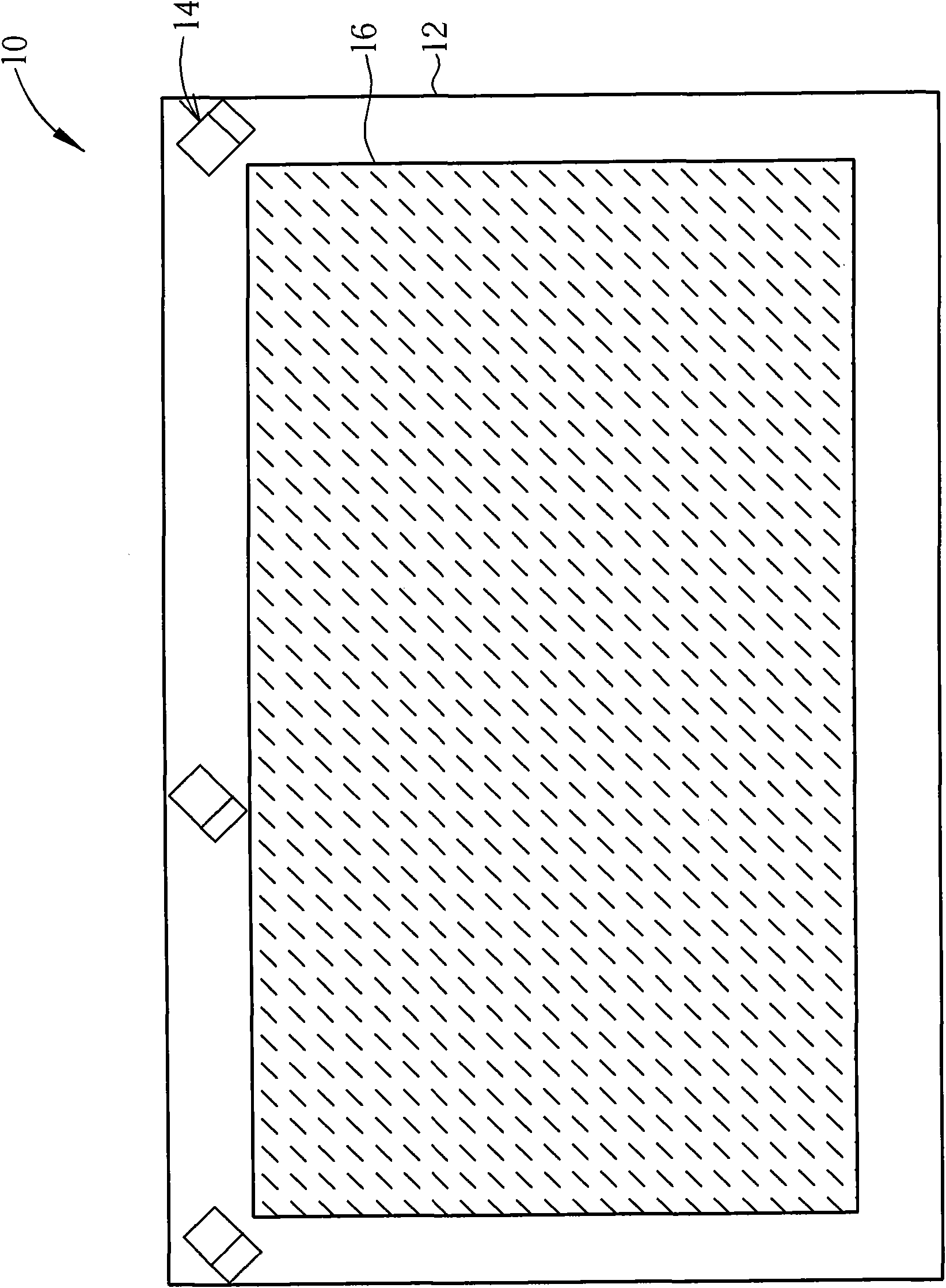
[0022] see figure 1 , which is a schematic diagram of an optical touch module 10 proposed according to an embodiment of the present invention. Depend on figure 1 It can be seen that the optical touch module 10 includes a screen 12 and at least one optical positioning device 14, figure 1 Three optical positioning devices 14 are shown, which are respectively disposed on the left top corner, the upper side and the right top corner of the screen 12, but not limited thereto. For example, the optical positioning device 14 may also be provided only on the top left corner and the top right corner of the screen 12 respectively, so as to simplify the configuration of the optical touch module 10 . The screen 12 has a touch surface 16 for a user to perform a touch operation.

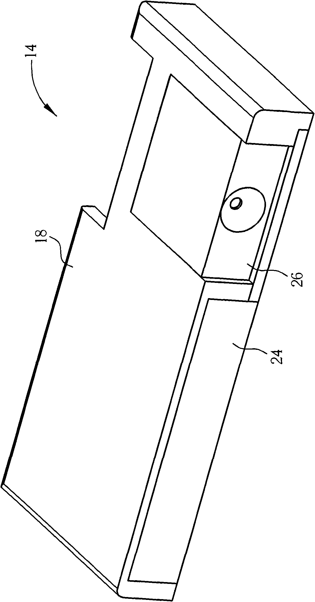
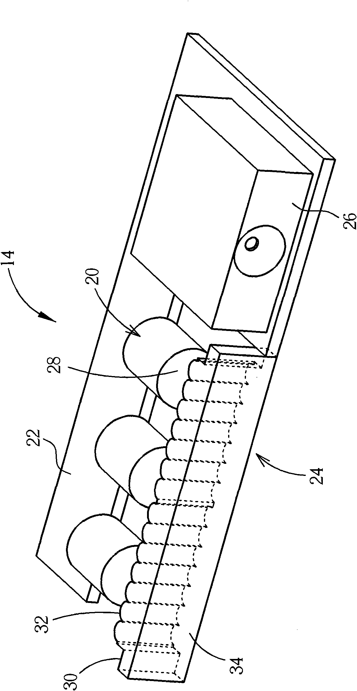
[0023] Next, see figure 2 as well as image 3 , figure 2 for figure 1 The schematic diagram of the appearance of the optical positioning device 14, image 3 for figure 2 Schematic diagram of the interior...


PUM


Abstract

An optical touch module includes a screen and at least one optical positioning device disposed on the screen. The optical positioning device includes a case, at least one light emitting unit, a circuit board, a transparent diffusing part and an image capturing unit. The light emitting unit is disposed on case for emitting invisible light. The circuit board is electrically connected to the light emitting unit for controlling the light emitting unit. The transparent diffusing part is disposed at a light emitting side of the light emitting unit. A bar structure is formed on a light entrance surface of the transparent diffusing part for scattering the invisible light to be distributed over a touch surface of the screen. The image capturing unit is disposed on the case to capture an optical image for a touch object on the touch surface when the touch object is illuminated by the invisible light.

Description

technical field [0001] The invention relates to an optical touch module, in particular to an optical touch module capable of increasing the light-emitting angle of a light-emitting unit. Background technique [0002] Generally speaking, the optical touch module usually uses the light reception blocking or direct imaging principle to detect the relative position of the finger on the touch surface, and its design uses two to three camera devices and near-infrared light emitting devices , The camera device is mostly placed on the left and right upper corners of the screen. The difference between these two methods is that the blocking imaging method uses background light (reflective side strips or near-infrared light-emitting side strips are set around the screen). After the program calculation, the coordinate position of the finger on the screen can be calculated; the direct image capture method is to directly irradiate the finger with near-infrared light, and after the image ...

Claims


Application Information

Patent Timeline
Patent Type & Authority Applications(China)
IPC IPC(8): G06F3/042
CPCG06F2203/04109G06F3/0428
Inventor 黄博亮刘家瑞
Owner WISTRON CORP
Learn More