Injection mold

A technology for injection molds and fixed templates, which is applied in the field of injection molds and can solve problems such as space occupation, complex structure of core-pulling mechanism, and difficult connection of parts

Active Publication Date: 2012-06-13
QINGDAO HAIER MOLDS
View PDF3 Cites 7 Cited by
  • Summary
  • Abstract
  • Description
  • Claims
  • Application Information

AI Technical Summary

Problems solved by technology

In the above technical solution, since the lock module is connected under the fixed mold frame and arranged between the fixed mold frame and the movable mold frame, the lock module will occupy the spac

Method used


Image

  • Injection mold
  • Injection mold
  • Injection mold

Examples


Embodiment Construction

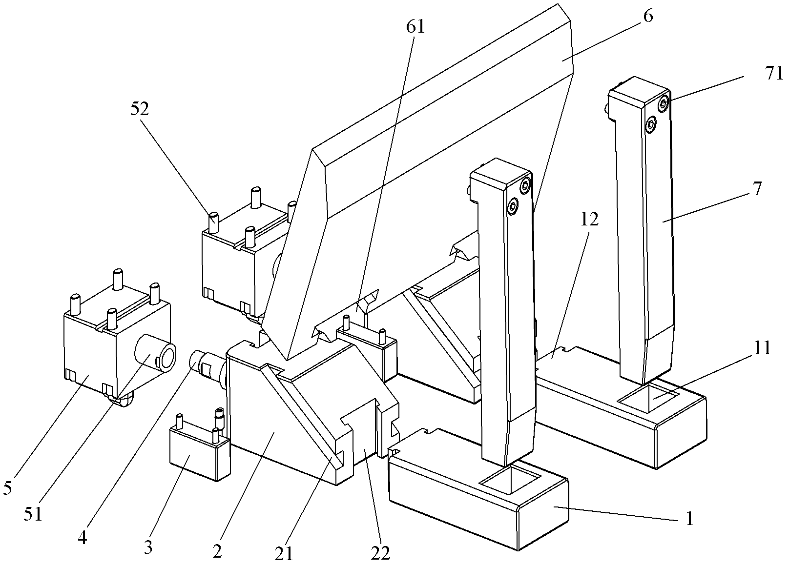
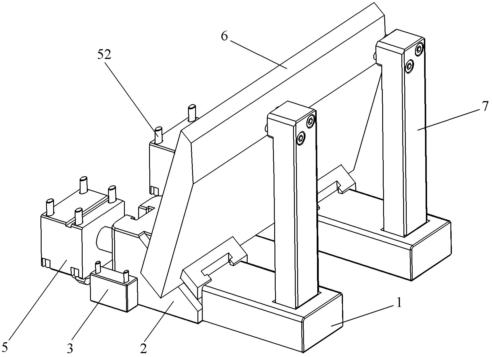
[0024] Combine below Figure 1-Figure 3 The injection mold proposed by the present invention will be described in detail.

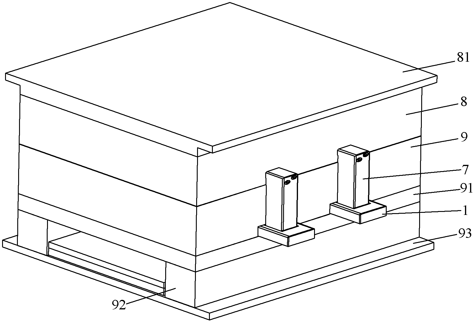
[0025] image 3 Shown is the overall schematic diagram of the locking mechanism on the injection mold, such as image 3 As shown, the injection mold is provided with a top plate 81, a fixed platen 8, a movable platen 9, a support plate 91, a mold foot 92 and a bottom plate 93 from top to bottom, wherein the top plate 81 and the fixed platen 8 are sequentially connected and fixed on the injection molding machine. On the fixed mold, it generally remains still during the injection molding process; the movable template 9, support plate 91, mold foot 92 and bottom plate 93 are sequentially connected and arranged on the movable mold of the injection molding machine. During the injection molding process, this part is relatively fixed template 8 It can move along the mold clamping direction, and in this embodiment, the mold clamping direction is the up and down...


PUM


Abstract

The invention provides an injection mold, which comprises a fixed mold and a moving mold. A core-pulling mechanism is disposed on the moving mold, a locking part is arranged on the outer side of the fixed mold, and a locking part fixing seat is disposed on the moving mold and connected with the core-pulling mechanism. One end of the locking part is connected with the fixed mold, and the other end of the locking part is movably connected with the locking part fixing seat. In addition, when the injection mold is in a state of mold closing, the locking part and the locking part fixing seat are in a state of connection so as to prevent the core-pulling mechanism from being beaten back due to overlarge injection force during an injection process. Due to the fact that the locking part is arranged on the outer side of the fixed mold, the arrangement of the locking part is not limited by space inside the mold, the problem that a locking mechanism is difficult to connect due to limit of space arrangement is resolved, and meanwhile the space inside the mold can be saved.

Description

technical field [0001] The invention relates to an injection mold. Background technique [0002] During the design process of injection molds, due to undercuts inside the plastic products, the products often cannot come out of the mold directly, and an oil cylinder core-pulling mechanism is required. If the surface area of ​​the product is large, a large injection force will be required, so that the core-pulling mechanism of the oil cylinder will be driven back during the injection molding process, resulting in defects such as flashes and burrs on the surface of the product. In view of this situation, it is necessary to strengthen the locking degree of the core-pulling mechanism to resist the impact of the injection force on the core-pulling mechanism. [0003] At present, the general locking mechanism is designed inside the injection mold. For example, the patent with the authorized announcement number of CN201755898U discloses a core-pulling and inverted demoulding mechan...

Claims


Application Information

Patent Timeline
IPC IPC(8): B29C45/26B29C45/33
Inventor 张平王涛黄俊
Owner QINGDAO HAIER MOLDS
Why Eureka
Try Eureka