
Floating offshore wind turbine movement suppression device and floating base for offshore wind turbine

一种海上风机、抑制装置的技术,应用在减少船只运动的设备、安装/支撑风力发动机的配置、发动机等方向,能够解决危及系统结构安全、影响风机正常运行、载荷不同等问题

Active Publication Date: 2012-06-13
GOLDWIND SCI & TECH CO LTD
View PDF7 Cites 26 Cited by
  • Summary
  • Abstract
  • Description
  • Claims
  • Application Information

AI Technical Summary

Problems solved by technology

[0006] However, the loads borne by the floating wind turbine foundations used in the field of offshore wind power are different from those of traditional ships and floating platforms in offshore oil engineering. In addition to bearing the combined effect of wind, wave and current, the floating offshore wind turbine foundations also have to bear the wind, wave and current. The gyroscopic effect caused by the operation of the towering structure will generate the overturning moments Mx, My and the torque Mz around the vertical axis of the wind turbine foundation, so that the entire wind turbine will produce violent movements in six degrees of freedom, including X, Y and Z axes The axial movement and the swing around the axis bring great challenges to the pitch and yaw control system of the wind turbine, which will affect the normal operation of the wind turbine, affect the power generation, and even endanger the safety of the entire system structure
[0007] Due to the different structural characteristics of floating wind turbine foundations from ships and floating platforms, the loads generated by the operation of the mechanical devices carried are also different. At present, there is no effective suppression device for the movement of offshore floating wind turbines.

Method used


Image

  • Floating offshore wind turbine movement suppression device and floating base for offshore wind turbine
  • Floating offshore wind turbine movement suppression device and floating base for offshore wind turbine
  • Floating offshore wind turbine movement suppression device and floating base for offshore wind turbine

Examples


Embodiment Construction

[0043] Hereinafter, embodiments of the present invention will be described in detail with reference to the drawings.

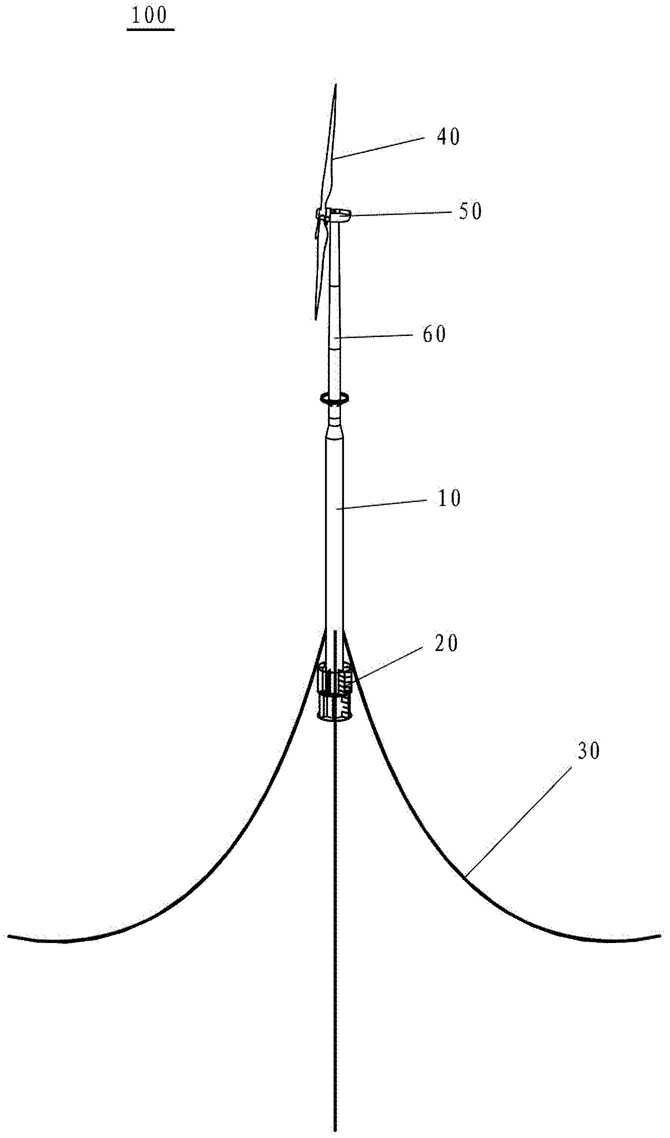
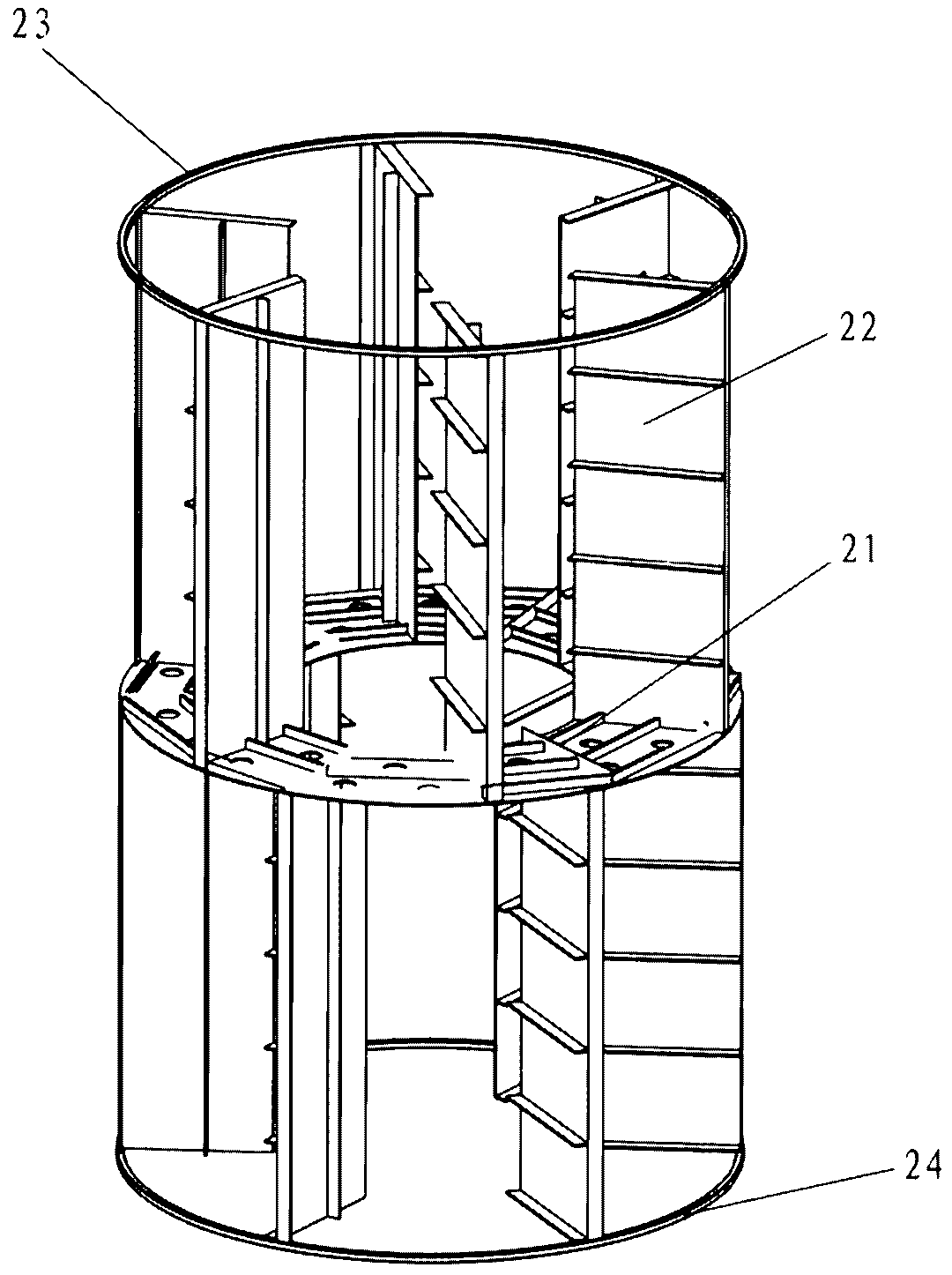
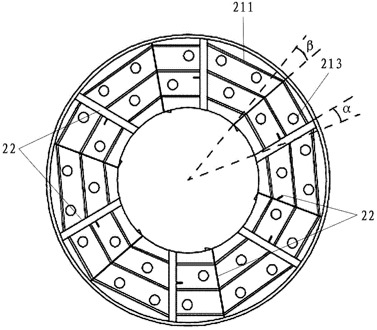
[0044] figure 1 is a perspective view showing a spar type floating foundation offshore wind turbine to which the motion suppressing device according to the first embodiment of the present invention is applied. figure 2 is a perspective view showing a motion suppressing device according to a first embodiment of the present invention. image 3 and Figure 4 are shown respectively figure 2 Plan and perspective views of the stabilizer plate of the motion suppression device in . Figure 5 is showing figure 2 A perspective view of the stabilizer fins of the motion suppression device in .

[0045] The motion suppression device according to the first embodiment of the present invention will be described below by taking a single-column floating foundation offshore wind turbine as an example.

[0046] Such as figure 1 As shown, the single-column floating found...


PUM


Abstract

The invention discloses a floating offshore wind turbine movement suppression device and a floating base with the same. The floating offshore wind turbine movement suppression device comprises at least one annular anti-rolling plate which surrounds the floating base and is horizontally arranged. A plurality of anti-rolling fins are arranged on the anti-rolling plate, and comprise a first group of anti-rolling fins which are arranged on one side of the anti-rolling plate; and the first group of anti-rolling fins are vertically spaced from one another around the floating base. The floating offshore wind turbine movement suppression device can effectively suppress the movement of a floating wind turbine, is low in cost and has a wide application prospect.

Description

technical field [0001] The present invention relates to an offshore wind power generator, in particular to a floating offshore wind turbine movement suppression device capable of suppressing the swing of the offshore wind turbine around a vertical axis and a floating offshore wind turbine movement suppression device with the floating offshore wind turbine movement suppression device Floating foundation for wind turbines. Background technique [0002] For offshore wind turbines, gravity foundations, single pile foundations, jacket and three-pillar foundations, caisson foundations and floating foundations are generally used according to seawater depth and seabed geological conditions. Among these types of wind turbine foundations, the installation of floating foundations is not limited by seabed conditions and can be applied to offshore wind farms with seawater depths exceeding 50 meters. Therefore, research on floating foundations has broad application prospects. [0003] Cl...

Claims


Application Information

Patent Timeline
Patent Type & Authority Applications(China)
IPC IPC(8): B63B38/00F03D11/00
CPCB63B38/00F05B2240/95Y02E10/722F03D11/04Y02E10/727F03D11/00F03D13/22B63B39/06B63B2039/067F05B2260/964B63B35/44B63B2035/446F03D13/25B63B2035/442F03D13/20Y02E10/72
Inventor 李荣富朱海飞白洛林石磊
Owner GOLDWIND SCI & TECH CO LTD
Learn More