Reusable die for equipment foundation reserved square hole

A technology of equipment foundation and square hole, which is applied in the direction of infrastructure engineering, formwork/formwork/working frame, and on-site preparation of building components. problem, to achieve the effect of improving the pull-out bearing capacity, reducing the labor intensity and reducing the construction cost

Active Publication Date: 2012-06-13
CHINA FIRST METALLURGICAL GROUP
View PDF6 Cites 7 Cited by
  • Summary
  • Abstract
  • Description
  • Claims
  • Application Information

AI Technical Summary

Problems solved by technology

The steel corrugated pipe adopts a tool with a slot at one end and a handle at the other end. The slot is clamped to the steel bellows, and the steel corrugated pipe is peeled off layer by layer. The removal effect is not satisfactory; the plastic pipe is baked at high temperature to make it soft, and then Pulling out as a whole, the method sometimes causes the plastic pipe to break off, which directly affects the strength of the secondary grouting of the anchor bolt holes; the wooden formwork adopts a square pyramid-shaped wooden box structure with a large upper opening and a smaller lower opening, with small cross-section and deep depth. For deep holes, there will be various difficulties such as difficulty in force and limited space when dismantling
In order to improve the pull-out bearing capacity of bolts, a structure with the lower opening slightly larger than the upper opening is often used. Steel bellows and plastic pipes are standard materials for pipe diameters, which cannot meet the requirements of large upper openings and smaller lower openings. The upper opening is smaller than the lower opening. The large pyramid-shaped wooden box cannot be dismantled even if it meets the size requirements
Namely: the anchor bolt hole is characterized by a long and narrow space with a large aspect ratio, so it brings great inconvenience to the demolition, and its formwork cannot be reused during the demolition process

Method used


Image

  • Reusable die for equipment foundation reserved square hole
  • Reusable die for equipment foundation reserved square hole
  • Reusable die for equipment foundation reserved square hole

Examples


Embodiment Construction

[0018] In order to better understand the present invention, the technical solutions of the present invention will be further described below in conjunction with the embodiments and the accompanying drawings.

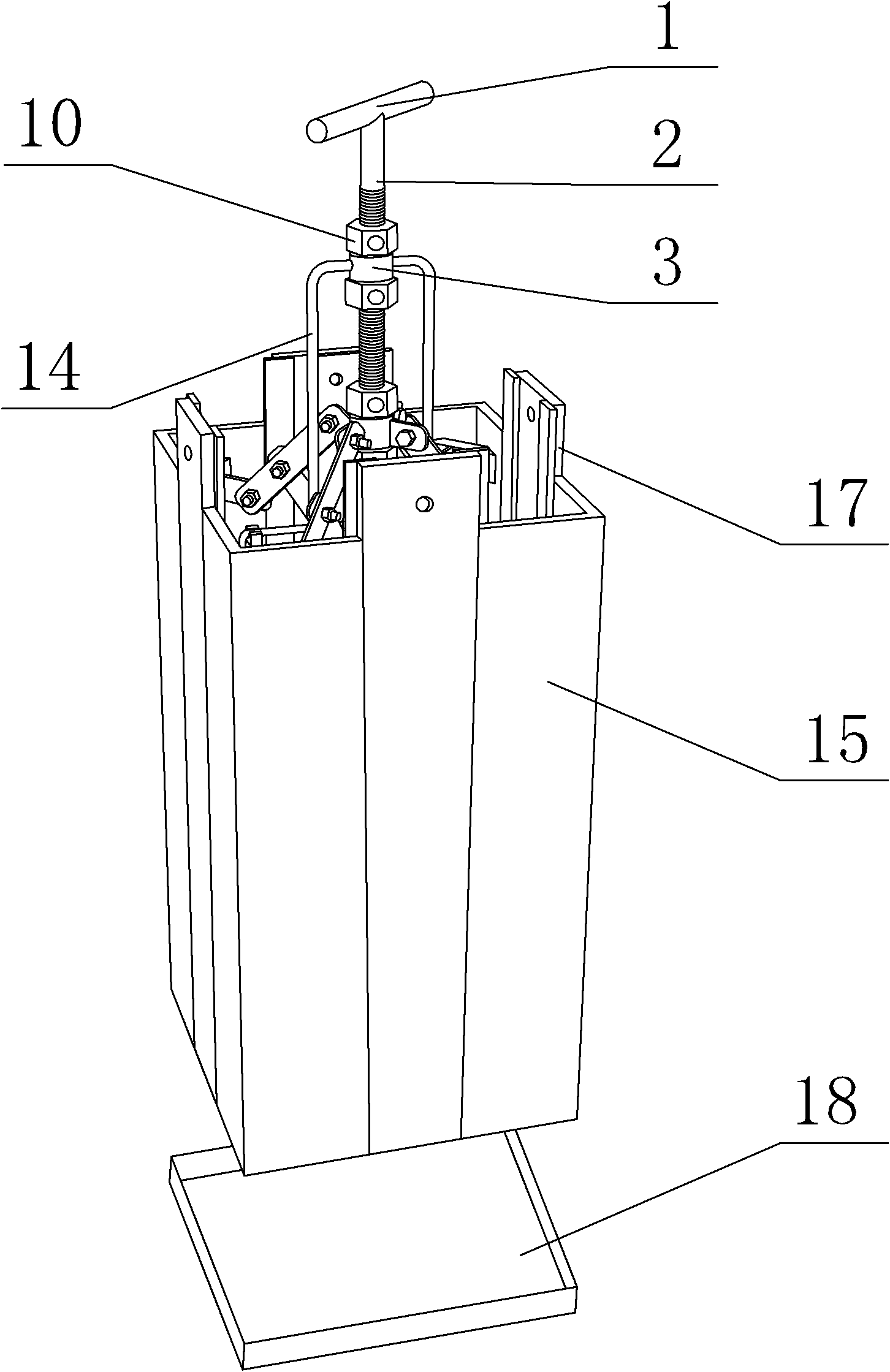
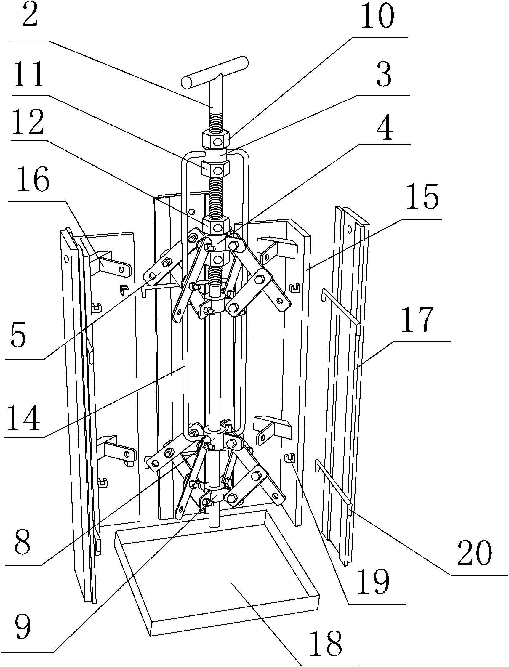
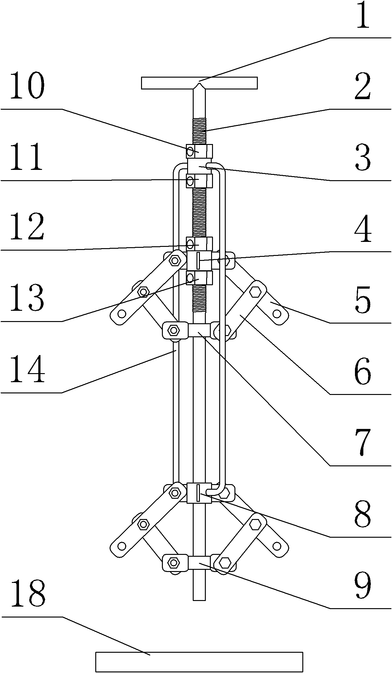
[0019] A reusable mold with square holes reserved for the equipment foundation, its structure is as follows Figure 1 to Figure 3 As shown, it includes a central axis 2, a first expansion and contraction device, a second expansion and contraction device, 4 corner templates 15, and 4 middle templates 17; 4 corner templates 15 are L-shaped at right angles, 4 The three corner templates 15 are distributed at 4 corners, the middle template 17 is inserted between the corner templates and the corner templates on the same side, the space surrounded by 4 corner templates 15 and 4 middle templates 17, 4 corner templates 15 Two formwork supports 16 (respectively the first formwork support and the second formwork support) are arranged on the inner side of the corner formwork, the fi...


PUM


Abstract

The invention belongs to a reusable die for an equipment foundation reserved square hole. The reusable die for the equipment foundation reserved square hole is characterized by comprising a central shaft, a first opening and shrinking device, a second opening and shrinking device, four corner die plates and four middle die plates, wherein the middle die plates are inserted between the corner die plates on the same side, the four corner die plates and the four middle die plates can enclose a square space, and the inner sides of the four corner die plates are all provided with two die plate supports; both the first opening and shrinking device and the second opening and shrinking device are arranged on the central shaft, first die plate supports of the four corner die plates are all articulated with the first opening and shrinking device, and second die plate supports of the four corner die plates are all articulated with the second opening and shrinking device; and the lower part of the central part, the first opening and shrinking device and the second first opening and shrinking device are all positioned in the square space enclosed by the four corner die plates and the four middle die plates. The die is simple to operate and can be quickly disassembled and reused.

Description

technical field [0001] The invention belongs to a reusable mold with square holes reserved for anchor bolt holes in the equipment foundation. Background technique [0002] In the construction of the equipment foundation, the foundation bolt holes of the equipment need to be reserved on the concrete foundation. The reserved method generally adopts the methods of supporting steel bellows, plastic pipes or supporting wooden formwork, etc., and removes them in time after the concrete solidifies. The steel corrugated pipe adopts a tool with a slot at one end and a handle at the other end. The slot is clamped to the steel bellows, and the steel corrugated pipe is peeled off layer by layer. The removal effect is not satisfactory; the plastic pipe is baked at high temperature to make it soft, and then Pulling out as a whole, the method sometimes causes the plastic pipe to break off, which directly affects the strength of the secondary grouting of the anchor bolt holes; the wooden fo...

Claims


Application Information

Patent Timeline
Patent Type & Authority Applications(China)
IPC IPC(8): E02D27/44E04G15/04
Inventor 王平夏春
Owner CHINA FIRST METALLURGICAL GROUP
Why Eureka
Try Eureka