Centralized lubrication mechanism for excavator working device

A working device and centralized lubrication technology, which is applied in the field of dry oil lubrication device and the centralized lubrication device of the hinged surface of the excavator working device, which can solve the problem of low efficiency of lubricating oil filling, inability to centrally add lubricating oil and lubricating oil. Inconvenience and other problems, to achieve the effect of improving work efficiency, shortening filling time, and simple structure

Inactive Publication Date: 2012-06-13
中外合资沃得重工(中国)有限公司
View PDF7 Cites 3 Cited by
  • Summary
  • Abstract
  • Description
  • Claims
  • Application Information

AI Technical Summary

Problems solved by technology

However, this utility model only moves the lubricating oil filling port of the stick cylinder to the lower part of the boom, which is still at a higher position from the ground. It is only suitable for small and medium excavators. Concentrated filling of lubricating oil, it is still inconvenient to add lubricating oil, and the efficiency of lubricating oil filling is low
The size of the components of the working device of a large excavator is much larger than that of a small and medium-sized excavator, and the lubrication points are far apart and higher than the ground. In order to add lubricating oil, the working device must change its position many times so that each lubrication point can be lowered to the operating position. The height required by the personnel can complete the lubricating oil filling, which affects work efficiency

Method used


Image

  • Centralized lubrication mechanism for excavator working device
  • Centralized lubrication mechanism for excavator working device
  • Centralized lubrication mechanism for excavator working device

Examples


Embodiment Construction

[0013] The present invention will be further described below in conjunction with drawings and embodiments.

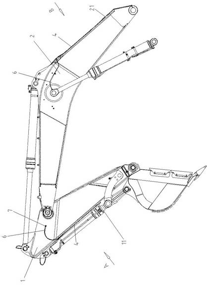
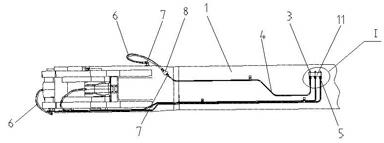
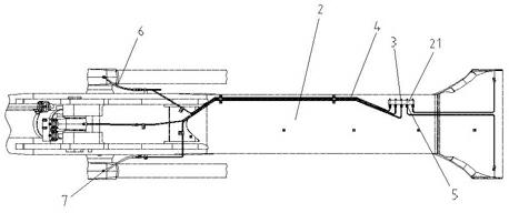
[0014] This example Figure 1 ~ Figure 3 As shown, it includes a first lubricating oil nipple integrated block 11 arranged in the lower end of the arm 1 , a second lubricating oil nipple integrated block 21 arranged in the lower end of the boom 2 , a plurality of lubricating oil nipples 3 , and a plurality of oil guide pipes 4 . Such as figure 2 As shown, three lubricating oil nipples 3 are fixed side by side on one side of the first lubricating oil nipple integrated block 11, and the other side of the first lubricating oil nipple integrated block 11 is respectively connected to one end of three oil guide pipes 4 through three oil pipe joints 5, 3 The other end of the root oil guide pipe 4 leads to the articulation surfaces of the corresponding joints of the arm oil cylinder and the boom oil cylinder through the flexible pipe 6 and the flexible pipe joint 7 respective...


PUM


Abstract

The invention discloses a centralized lubrication mechanism for an excavator working device, which comprises a plurality of lubricating oil nozzle manifold blocks, a plurality of lubricating oil nozzles and a plurality of oil ducts, wherein the lubricating oil nozzle manifold blocks are respectively arranged in the lower end of a bucket rod or the lower end of a swing arm; the lubricating oil nozzles are respectively fixed on one sides of the lubricating oil nozzle manifold blocks; one ends of the oil ducts are respectively fixed on the other side surfaces of the lubricating oil nozzle manifold blocks by oil duct joints and are communicated with the corresponding lubricating oil nozzle via the respective oil line in each lubricating oil nozzle manifold block; and the other ends of the oil ducts are respectively introduced to the hinged surface of each movable joint of the working device via hoses and hose joints. The centralized lubrication mechanism for the excavator working device has the advantages of simple structure and high integration degree, lubricating oil can be conveniently injected into the lubricating oil nozzle manifold blocks on the lower end of the bucket rod and the lower end of the swing arm only by lowering the swing arm and the bucket rod once, so that the lubricating oil filling efficiency is greatly improved, the lubricating oil filling time is shortened, and therefore, the working efficiency of an excavator is improved.

Description

technical field [0001] The invention relates to a dry oil lubricating device for engineering machinery, in particular to a centralized lubricating device for the hinged surface of an excavator working device, which belongs to the technical field of engineering machinery. Background technique [0002] An excavator is an earth-moving machine that uses a bucket to excavate soil or materials that are higher or lower than the bearing surface, and load it into a transport vehicle or unload it to a stockyard. After the excavator working device is replaced with the corresponding attachment, it can also be used for concrete Demolition and debris transfer of components or road surfaces. The excavator operates in the harsh environment with a lot of dust in the open air. During the operation, the working oil cylinders of each joint expand and contract repeatedly, and the movable joints rotate frequently. Rotation is not flexible, and then affects the normal operation of the whole devic...

Claims


Application Information

Patent Timeline
Patent Type & Authority Applications(China)
IPC IPC(8): E02F9/24
Inventor 殷晴飞
Owner 中外合资沃得重工(中国)有限公司
Why Eureka
Try Eureka