LED (light emitting diode) lamp bulb

A technology of LED light bulbs and lamp holders, which is applied in the LED field, can solve the problems that the luminous effect cannot reach that of incandescent lamps, affect the lighting effect, and the illumination angle is not high, etc., and achieve the effects of improving service life, convenient welding and enlarging the lighting area

Inactive Publication Date: 2012-06-13
德清鼎辉照明有限公司
View PDF3 Cites 5 Cited by
  • Summary
  • Abstract
  • Description
  • Claims
  • Application Information

AI Technical Summary

Problems solved by technology

[0003] However, LED has the disadvantage of low illumination angle, and its limited illumination angle will cause some areas around the LED to form a lighting blind area, which affects its lighting effect. Although it can save energy and have a long service life, the luminous effect sometimes does not reach to the effect of an incandescent lamp

Method used


Image

  • LED (light emitting diode) lamp bulb
  • LED (light emitting diode) lamp bulb
  • LED (light emitting diode) lamp bulb

Examples


Embodiment

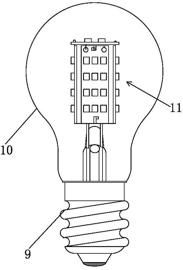
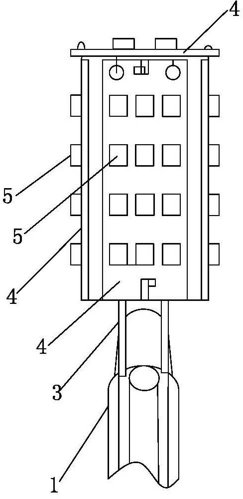
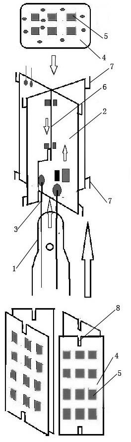
[0022] Embodiment: a kind of LED light bulb, as figure 1 As shown, including a lamp holder 9 and a bulb shell 10, a glass stem 1 and a light-emitting stem 11 are arranged in the bulb shell 10, as figure 2 , 3 As shown, the luminous stem 11 includes two aluminum substrates 2, and the two aluminum substrates 2 are cross-fixed together. An LED drive circuit is welded on the aluminum substrate 2, and a wire 3 is drawn out of the glass stem 1. , the wire 3 is welded and fixed to the lower end of one of the aluminum substrates 2, a circuit board 4 is fixed on the left and right sides of each aluminum substrate 2, the plane where the circuit board 4 on the side of the aluminum substrate is located and the aluminum substrate 2 connected to it The planes are vertical, and a circuit board 4 is also fixed on the tops of the two aluminum substrates 2, and the planes of the circuit boards 4 on the tops of the two aluminum substrates 2 are perpendicular to the respective planes of the two...


PUM


Abstract

The invention discloses an LED lamp bulb. The lamp bulb comprises a lamp cap and a bulb shell, wherein a glass stem and an illumination stem are arranged in the bulb shell; the illumination stem comprises two aluminum substrates which are fixed together in a crossing manner; a lead wire extracted from the glass stem is fixed at the lower end of the aluminum substrates in a soldering way; circuit boards are fixed on left and right sides of each aluminum substrate respectively; the plane of the circuit board on the lateral part of the aluminum substrate is vertical to the plane of the aluminum substrate connected with the circuit board; a circuit board is fixed at the top end of the two aluminum substrates; and a plurality of LED chips are soldered on the circuit boards on lateral sides of the aluminum substrates and the circuit board at the top end of the two aluminum substrates. In the illumination stem, the two aluminum substrates are fixed together in a cross splicing manner, a circuit board is fixed on each side of each aluminum substrate, a circuit board is arranged at the top part of the two aluminum substrates, and LED chips are fixed on the circuit boards, so that the stem forms a rectangular luminous block, and the lighting area is enlarged to form dead zone free lighting.

Description

technical field [0001] The invention relates to the technical field of LEDs, in particular to an LED light bulb. Background technique [0002] Energy saving and emission reduction is a hot spot in the world today. Due to the rapid development of LEDs, it is an inevitable trend to replace incandescent lamps with LEDs. [0003] However, LED has the disadvantage of low illumination angle, and its limited illumination angle will cause some areas around the LED to form a lighting blind area, which affects its lighting effect. Although it can save energy and have a long service life, the luminous effect sometimes does not reach to the effect of an incandescent lamp. Contents of the invention [0004] The present invention overcomes the shortcomings in the above-mentioned prior art, and provides an LED light bulb that can increase the luminous angle, expand the irradiation range, and can replace the incandescent light bulb. [0005] Technical scheme of the present invention is ...

Claims


Application Information

Patent Timeline
Patent Type & Authority Applications(China)
IPC IPC(8): F21S2/00F21V19/00F21Y101/02
Inventor 马人秀钟建华
Owner 德清鼎辉照明有限公司
Why Eureka
Try Eureka