Measuring system of swing angle of swing nozzle and measuring method of swing angle

A technology of swing angle and measurement method, applied in the direction of measurement device, measurement angle, mapping and navigation, etc., can solve the problem that the nozzle cannot use tooling equipment and contact sensors.

Active Publication Date: 2014-06-04
BEIJING INST OF ELECTRONICS SYST ENG
View PDF1 Cites 0 Cited by
  • Summary
  • Abstract
  • Description
  • Claims
  • Application Information

AI Technical Summary

Problems solved by technology

However, when the nozzle is in a fully assembled state, due to space constraints, it is obviously impossible to use tooling equipment for the nozzle, so that the contact sensor cannot be used

Method used


Image

  • Measuring system of swing angle of swing nozzle and measuring method of swing angle
  • Measuring system of swing angle of swing nozzle and measuring method of swing angle
  • Measuring system of swing angle of swing nozzle and measuring method of swing angle

Examples


specific Embodiment approach 1

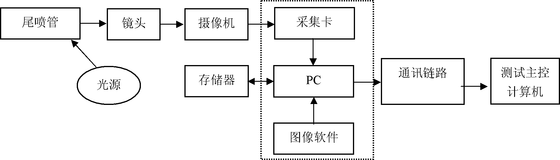
[0022] Embodiment one: the measurement system of the swing angle of the swing nozzle described in this embodiment includes an image acquisition device and an image processing computer, the image acquisition device is used to continuously collect the image information of the tail nozzle to be measured, and collect The received image information is sent to an image processing computer, and the image processing computer is used to process the received image information, and obtain the swing angle information of the tail nozzle to be tested according to the continuously collected image information.

[0023] The image acquisition device is generally fixed by a tripod, so that the lens direction of the image acquisition device can be adjusted in any direction with any degree of freedom in three-dimensional space.

[0024] The image resolution of the image acquisition device in this embodiment is not lower than 1024×1024, and the image acquisition rate is not lower than 50 fps.

[00...

specific Embodiment approach 2

[0038] Specific embodiment 2: This embodiment is to further limit the image acquisition device in the measurement system for the swing angle of the oscillating nozzle described in the specific embodiment 1. The image acquisition device described in this embodiment consists of an auxiliary light source and Composed of camera equipment, the camera equipment is realized by an image acquisition device with a high-speed image transmission interface, and the camera equipment is connected with an image processing computer through the high-speed image transmission interface; the auxiliary light source is used to irradiate the tail nozzle to be tested, Provide auxiliary light source for camera equipment.

[0039] Since the field of view of the nozzle is relatively large and the speed of the nozzle is relatively high, the brightness in the field of view has a great influence on the image quality when taking pictures. Therefore, it is necessary to supplement light to the field of view of ...

specific Embodiment approach 3

[0054] Specific Embodiment 3. The description in this embodiment is the description of the measurement process of the swing angle by using the swing angle measurement system of the swing nozzle according to the present invention.

[0055] The measurement process described in this embodiment is:

[0056] First perform the step of calibrating the measuring system, and then start the step of measuring the swing angle of the tail nozzle, which is executed cyclically in the following two steps:

[0057] The step of collecting the image of tail nozzle;

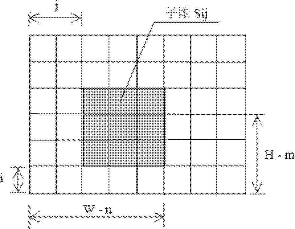
[0058] A step of calculating and obtaining the swing angle of the tail nozzle to be tested at the moment according to the collected images.


PUM


Abstract

A measuring method of the swing angle of a swing nozzle relates to an angle measuring technology, specifically to a measuring technology of the swing angle of the swing nozzle. By the adoption of the measuring technology, the swing angle of the assembled nozzle can be measured. The measuring method is realized based on the measuring system, in the measuring system, an image acquisition device is used to continuously acquire image information of the nozzle to be measured and send the acquired image information to an image processing computer. The image processing computer is used to process the received image information and acquire swing angle information of the nozzle to be measured according to the continuously acquired image information. According to the measuring method, the step of calibrating the measuring system is firstly carried out, followed by the step of measuring the swing angle of the nozzle. The steps are the following two steps which are carried out repeatedly: firstly, the step of acquiring the image of the nozzle; and secondly, the step of calculating the swing angle of the nozzle to be measured according to the acquired image. The invention is suitable for measuring the swing angle of the assembled nozzle.

Description

technical field [0001] The invention relates to an angle measurement technology, specifically designed to a measurement technology for the swing angle of a swing nozzle. Background technique [0002] In the prior art, in the measurement of the angle of the nozzle in the unassembled state, the measurement can be realized by placing a displacement sensor or an acceleration sensor on the nozzle. In this case, the assistance of larger-sized tooling equipment is required. However, when the nozzle is in a fully assembled state, due to space constraints, the nozzle obviously cannot use tooling equipment, so that the contact sensor cannot be used. Contents of the invention [0003] In order to realize the measurement of the swing angle of the assembled spray pipe, the present invention designs a method for measuring the swing angle of the swing spray pipe. [0004] The measurement method of the swing angle of the present invention is realized based on the following measurement sy...

Claims


Application Information

Patent Timeline
Patent Type & Authority Patents(China)
IPC IPC(8): G01C1/00
Inventor 顾彬彬邵云峰朱瑾李金波秦建尊吕东明
Owner BEIJING INST OF ELECTRONICS SYST ENG
Why Eureka
Try Eureka