Control device of fuel injection device

A technology of a fuel injection device and a control device, which is applied in the directions of fuel injection device, fuel injection control, valve device, etc., can solve problems such as flow difference

Active Publication Date: 2018-04-17
HITACHI ASTEMO LTD
View PDF14 Cites 2 Cited by
  • Summary
  • Abstract
  • Description
  • Claims
  • Application Information

AI Technical Summary

Problems solved by technology

However, when the requirements for exhaust gas become stricter, the flow rate will vary due to the charact...

Method used


Image

  • Control device of fuel injection device
  • Control device of fuel injection device
  • Control device of fuel injection device

Examples


Embodiment Construction

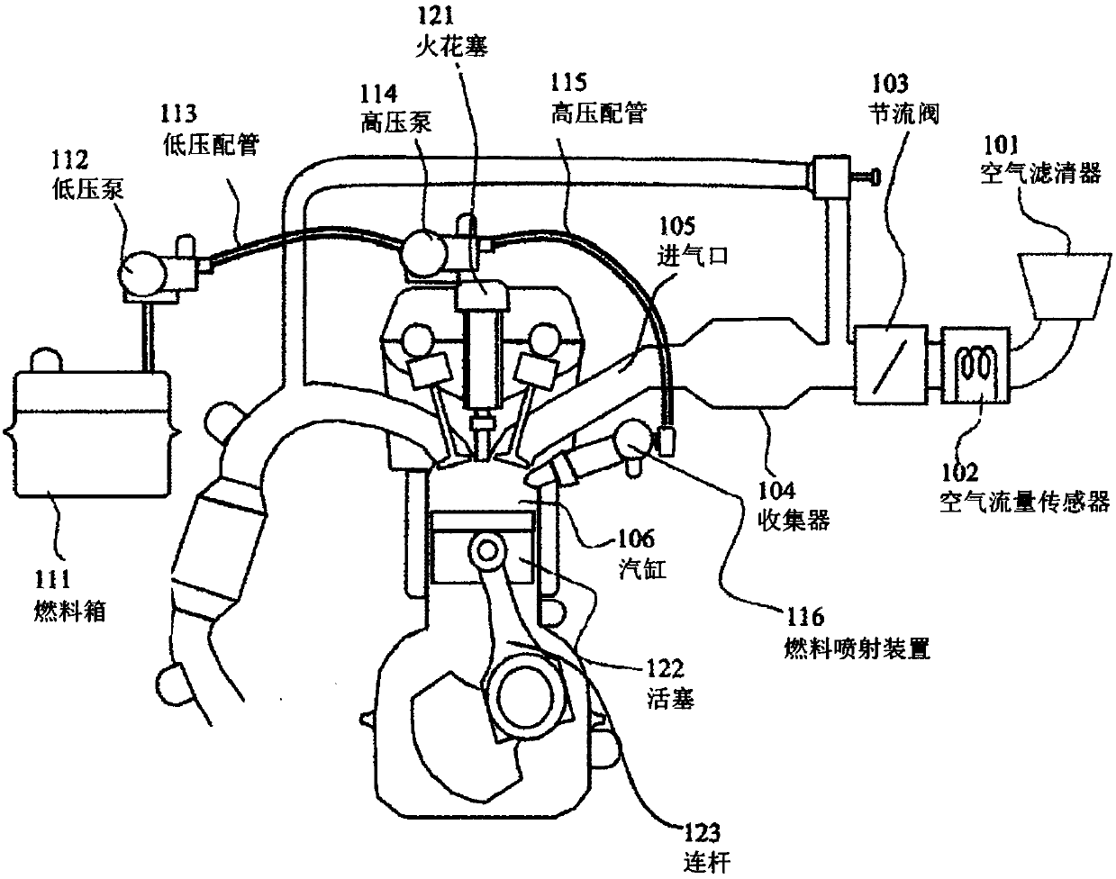
[0029] figure 1 An internal combustion engine equipped with a fuel injection device controlled by a control device according to the invention is shown. In the internal combustion engine, air and fuel are sucked into the cylinder 106, and these mixed gases are ignited by the spark plug 121 to explode, and the piston 122 reciprocates due to the energy of the explosion. This reciprocating motion is converted into rotational motion of the crankshaft by a link mechanism including the link 123 and the like, and becomes a driving force for moving the vehicle.

[0030] The air is filtered by the air filter 101 , the flow rate is adjusted by the throttle valve 103 , and flows into the cylinder 106 through the collector 104 and the intake port 105 . An air flow sensor 102 is provided between the air cleaner 101 and the throttle valve 103, and measures the amount of air taken in by the internal combustion engine. On the other hand, the fuel in the fuel tank 111 is sent to the low-press...


PUM


Abstract

According to the present invention, the force of a set spring is estimated with a high precision, as a result of which a drive waveform is adjusted. This control device of a fuel injection device is characterized in comprising: a reading means for reading a drive voltage of a solenoid; an inflection point extracting filter which filters the drive voltage to emphasize inflection points; a means forselecting the latest inflection point from among the extracted inflection points, or a means for calculating the time difference between the latest inflection point and the earliest inflection point;and a drive current adjusting means for adjusting a drive current parameter on the basis of the timing of the selected latest inflection point or the time difference between the inflection points.

Description

technical field [0001] The present invention relates to a control device for reducing individual differences in fuel injection devices that supply fuel to internal combustion engines. Background technique [0002] As a driving method of a fuel injection device of an existing direct injection internal combustion engine, an injection amount requested from the internal combustion engine is injected based on a preset drive current distribution and a drive pulse Ti of a fuel injection valve. However, when the requirements for exhaust gas become stricter, the flow rate will vary due to the characteristics of each fuel injection device even if the same drive current distribution and drive pulse Ti are given. Therefore, a method to reduce this difference is proposed. [0003] For example, in Patent Document 1, a drive control device for a solenoid valve that controls the flow of fluid is proposed, which is characterized in that it includes: a terminal voltage detection unit that de...

Claims


Application Information

Patent Timeline
IPC IPC(8): F02D41/20F02M51/00F02M51/06F16K31/06
CPCF02M51/00F02M51/06F16K31/06F02D2041/2055F02D41/20F02D41/2467F02D2041/2003F02D2041/2051F02M51/061F16K31/0675
Inventor 青野俊宏丰原正裕向原修
Owner HITACHI ASTEMO LTD
Why Eureka
Try Eureka