Automatic testing device of make-and-break of superconducting coil quench protection signal transmission line in fusion device

A technology of signal transmission line and superconducting coil, applied in the direction of fault location, etc., can solve the problems of delaying the experiment process, affecting the stable operation of the quench protection system, etc., to achieve the effect of improving work efficiency, friendly interface and simple operation

Inactive Publication Date: 2012-06-13
INST OF PLASMA PHYSICS CHINESE ACAD OF SCI
View PDF4 Cites 5 Cited by
  • Summary
  • Abstract
  • Description
  • Claims
  • Application Information

AI Technical Summary

Problems solved by technology

Before the experiment, it is not only necessary to test the on-off of the original quench protection signal transmission line, but also to accurately test the zero point and accuracy of these nearly 100-channel fiber-optic isolation amplifiers, so as to minimize the disconnection (or short circuit) and The leakage protection and false protection caused by the unstable performance of the isolation amplifier, the former will cause the superconducting magnet or some important parts associated with it to be damaged or burned, and the latter will affect the stable operation of the quench protection system and delay the entire experiment process

Method used


Image

  • Automatic testing device of make-and-break of superconducting coil quench protection signal transmission line in fusion device
  • Automatic testing device of make-and-break of superconducting coil quench protection signal transmission line in fusion device
  • Automatic testing device of make-and-break of superconducting coil quench protection signal transmission line in fusion device

Examples


Embodiment Construction

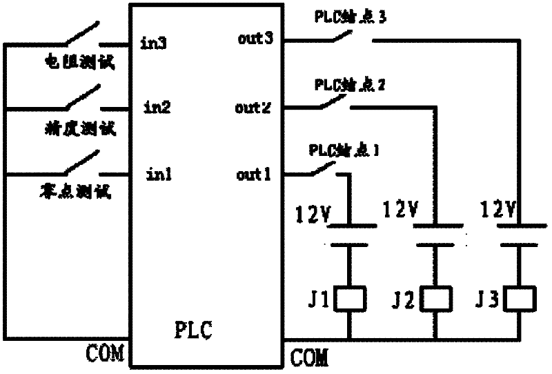
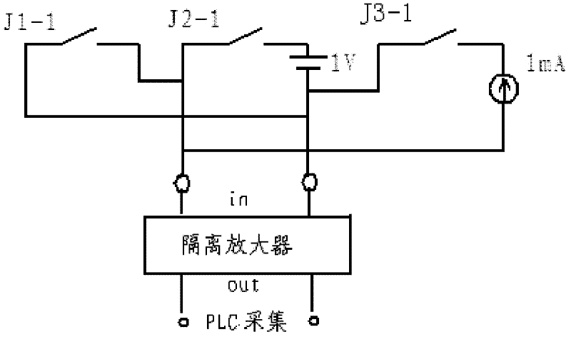
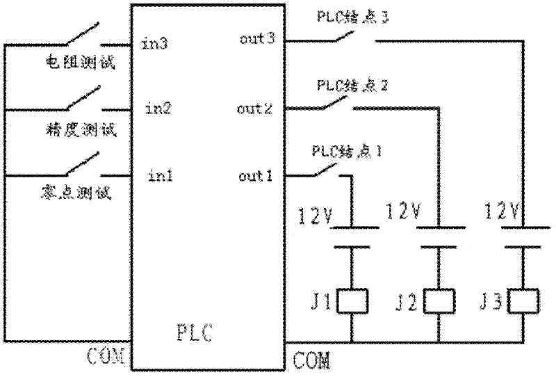
[0015] The automatic test device for the on-off of the superconducting coil quench protection signal transmission line in the fusion device includes a main control device PLC and an isolation amplifier. The main control device PLC includes an analog input module, three input terminals and their corresponding Three output terminals, the three input terminals are respectively connected with a switch, the other end of the three switches is connected to the common terminal COM of the main control device PLC, and the three output terminals are respectively connected in series with PLC nodes, DC power supply block and relay, the relays are J1, J2, J3 respectively, the other ends of the relays J1, J2, J3 are connected to the common terminal COM of the main control device PLC; the relays J1, J2, J3 respectively include a Normally open terminals J1-1, J2-1, J3-1, the J1-1 is connected in parallel with the isolation amplifier, the J2-1 is connected in parallel with the isolation amplifie...


PUM


Abstract

The invention discloses an automatic testing device of make-and-break of superconducting coil quench protection signal transmission line in a fusion device, which includes a master control equipment PLC (programmable logic controller) and an isolation amplifier, wherein the PLC includes an analog quantity input module, three input ends and three output ends corresponding to the input ends; the three input ends are connected with three switches respectively; the other ends of the three switches are connected with a common end of the PLC; the three output ends are connected in series with a PLCnodal point, a DC power module and a relay; the other end of the relay is connected with the common end of the PLC; the relay includes normal open ends J1-1, J2-1 and J3-1 respectively; the J1-1 is connected in parallel with the isolation amplifier; the J2-1 is connected in series with a constant voltage source and connected in parallel with the isolation amplifier; the J3-1 is connected in series with a constant current power and then connected with the isolation amplifier in parallel; the output signals of the isolation amplifier are connected into the analog quantity input module of the PLC; the PLC is in cable connection with a host computer monitor and display interface through a communication interface PPI; and the information collected by the master control equipment PLC is displayed through the host computer monitor and display interface. The automatic testing device has a friendly interface, is simple to operate, can store and search data at any time, and facilitates further analyzing and problem solving.

Description

technical field [0001] The invention relates to the field of on-off of a superconducting coil quench protection signal transmission line, in particular to an automatic test method for the on-off of a superconducting coil quench protection signal transmission line in a fusion device. Background technique [0002] The invention relates to a quench protection system in a fusion device. Even if the superconducting magnets of all superconducting tokamaks are within the range of their designed operating parameters, quenching will occur under certain operating conditions (superconducting coils from superconducting state to Normal state transition), if the quench protection cannot be performed in time, the energy stored in the magnet will be discharged, and the superconducting magnet or some important components associated with it will be damaged or burned. One end of the original quench protection signal in the EAST fusion device is taken from the superconducting coil, and the othe...

Claims


Application Information

Patent Timeline
Patent Type & Authority Applications(China)
IPC IPC(8): G01R31/08
Inventor 朱则英龚先祖胡燕兰潘超郑龙贵肖业政
Owner INST OF PLASMA PHYSICS CHINESE ACAD OF SCI
Why Eureka
Try Eureka